Transcription of July 1990 Types 95L and 95H Pressure Regulators
1 Types 95L and 95HD100256X012 Instruction ManualForm 1151 July 95L and 95H Pressure RegulatorsRegulators should be installed, oper-ated, and maintained in accordance withfederal, state, and local codes, rules andregulations, and Fisher the regulator vents gas or a leakdevelops in the system, it indicates thatservice is required. Failure to take theregulator out of service immediately maycreate a hazardous a serviceman in case of a qualified person must install orservice the 95L and 95H self-contained Pressure regulatorsare suitable for Pressure control of steam, air, gas,water, oil, and similar fluids requiring constant outletpressures between 2 and 150 psig. TypicalType 95L and95H Regulators are shown in figure 95L Pressure reducing regulator suitable forcontrolling many gasses and liquids. Iron, steel orstainless steel bodies are available.
2 Reduced pressurerange is from 2 to 30 psig with three different springsavailable. Body sizes 1/4 through 1-inch NPT, 1/2through 1-inch ANSI classes 150 and 300 flanges, and1/2 through 1-inch socket weld end connections areavailable. The standard orifice sizes are 1/4, 3/8 and 9/16-inch diameter, dependent on body 95H Basically same as 95L, but permits higherreduced Pressure ranges from 15 to 150 psig for the 1/4, 1/2, 3/4 and 1-inch sizes. Also available in 1-1/2 and2-inch NPT, ANSI class 150 or 300, or socket weldbodies with a 1-1/16-inch orifice to give reduced pres-sure ranges from 5 to 150 Of OperationPressure in the controlled system (regulator outletpressures) registers beneath the diaphragm of theregulator and opposes the force provided by the pre-Figure 1. Type 95L NPT Body (Left), Type 95H NPT Body (Middle), and Type 95H Flanged Body (Right) Pressure RegulatorsW1888W1888W5652 Types 95L and 95H2determined spring compression.
3 When regulator springforce exceeds diaphragm force exerted by the outletpressure, the spring will keep the stem pressed down,thereby compressing the valve spring and holding thevalve plug away from the orifice to permit additional flowto the downstream outlet Pressure increases to the setting of theregulator spring, the diaphragm is raised, and the valvespring moves the valve plug closer to the orifice toprevent additional buildup of outlet out all pipelines before installation of the regulatorand check to be sure the regulator has not beendamaged or collected foreign material during pipe compound to the male pipe threads andinstall the regulator in any position desired, but be sureflow through the body is in the direction indicated by thearrow cast on the is important that the regulator beinstalled so that the vent hole in thespring case is unobstructed at all outdoor installations, the regulatorshould be located away from vehiculartraffic and positioned so that water, ice,and other foreign materials cannot enterthe spring case through the vent.
4 Avoidplacing the regulator beneath eaves ordownspouts, and be sure it is above theprobable snow 1-1/2 or 2-inch Type 95H Regulators , the spring casevent is tapped so a vent line can be connected toprovide venting to a remote location. On 1/4, 1/2, 3/4and 1-inch Type 95H body sizes the tapped vent optionis available on request. The exposed end of the ventpipe should be protected with a weather and insectresistant vent vents and remote vent lines should be checkedperiodically to ensure that they are ProtectionAs is the case with most Regulators , the Type 95L and95H Regulators have an outlet Pressure rating lower thanthe inlet Pressure rating. The recommended pressurelimitations are stamped on the regulator nameplate. Sometype of overpressure protection is needed if the actual inletpressure exceeds the maximum operating outlet pressurerating.
5 Overpressure protection should also be provided ifthe regulator inlet Pressure is greater than the safe workingpressure of downstream operation below the maximum pressurelimitations does not preclude the possibility of damagefrom external sources or from debris in the line. Theregulator should be inspected for damage after any overpressure condition as stated on the regulator is set at the factory for the reducedpressure specified on the order, so no initial adjustmentshould be required to give the desired results. Withproper installation completed and relief valves properlyadjusted, slowly open the upstream and downstreamshutoff factory setting of the regulator can be varied withinthe Pressure range stamped on the nameplate. Tochange the outlet Pressure , loosen the locknut (key 17,figure 2, 3, or 4) and turn the adjusting screw (key 15,figure 2, 3, or 4) clockwise to increase outlet Pressure ,or counterclockwise to decrease it.
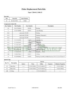
6 Monitor the outletpressure with a test gauge during the the locknut to maintain the desired regulator springs can be backed off to provide zerooutlet. Recommended outlet Pressure ranges available,maximum inlet pressures and temperatures, maximumemergency outlet pressures, and color codes of therespective springs are shown in tables 1 through 2. Maximum Inlet Pressure and TemperatureEPYTREBMUNYDOBLAIRETAMMGARHPA IDEVLAVDNAGULPLAIRETAMTELNIMUMIXAMDNAERU SSERP,ERUTAREPMET(F TAGISPrab)C TAL59,H59L59,H59L59,H59L59,H59L59,H59L59 ,H59noritsaCnoritsaCleetSleetSnoritsaCle etSenerpoeNleetssselniatSleetssselniatSe nerpoeNremotsaleoroulFremotsaleoroulF 081ta052 014ta052 054ta003 081ta003 003ta052 003ta003) 28ta2,71() 012ta2,71() 232ta7,02() 28ta7,02() 541ta2,71() 541ta7,02(YDOB,EZISSEHCNIGNIRPSROLOCEDOC DECUDERL59 EPYT,EGNARERUSSERP(GISPrab)DECUDERH59 EPYT,EGNARERUSSERP(GISPrab),2/1,4/11,4/3 wolleYneerGdeR6ot251ot503ot31)14,0ot41,0 ()30,1ot43,0()70,2ot09,0(03ot5157ot52051 ot07)70,2ot30,1()71,5ot27,1()3,01ot28,4( ,2 )25,5ot43,0()72,8ot41,4()56,9ot9,6()3,01 ot72,8(Table 1.
7 Reduced Pressure RangesTypes 95L and 95H3 ShutdownClose the upstream shutoff valve. Close downstreamshutoff valve. Open bleed valve between the regulator andthe downstream shutoff valve. Without changing regulatorspring adjustment, all Pressure between the upstreamand downstream shutoff valves will be released throughthe bleed valve, since the Type 95L or 95H opens inresponse to the decreased outlet disassembling the regulator,isolate it from the Pressure system andrelease all Pressure from the regulatoras specified in the section to normal wear that may occur, parts must beperiodically inspected and replaced if necessary. Thefrequency of inspection depends on the severity ofservice conditions. This section includes instructions fordisassembly and replacement of parts. All key numbersrefer to figures 2, 3, and Unscrew the valve plug guide (key 5) from the body(key 1).
8 The valve plug spring (key 10) and the valve plug(key 4) will normally come out of the body along withthe valve plug guide. On 1-1/2 or 2-inch units the stem(key 6, figure 4) will also come out of the regulator Inspect the seating surface of the valve plug, beingsure that the composition surface (or polished steelsurface) of the valve plug is not damaged. Replace ifdamage is Inspect the seating edge of the orifice (key 3). Ifdamage is noted, unscrew the orifice from the body andreplace it with a new part. Torque per table 4. If nofurther maintenance is required, reassemble the regula-tor in the reverse of the above steps. When installingthe valve plug guide (key 5) coat the threads andsealing surface with sealant to ensure an adequatemetal-to-metal seal. Reassembly torque per table If diaphragm damage is suspected, or to inspectthe diaphragm or other internal parts, loosen the locknut(key 17) and turn the adjusting screw (key 15) toremove all spring 5 and 6 apply to the Type 95L and sizes 1/4 to 1-inch Type 95H.
9 If the unit being disassembled is a 1-1/2to 2-inch size Type 95H, proceed to Steps 7 and Remove the diaphragm case cap screws (key 16)and lift off the spring case (key 2). Remove the upperspring seat (key 9) and regulator spring (key 11). On 1/4to 1-inch sizes Type 95H units only, remove the lowerspring seat (key 8). On 95L units, remove the dia-phragm head assembly (key 21).6. Remove the diaphragm(s) and examine for if damage is noted. Note that if the diaphragmis metal, two diaphragms should be Remove the diaphragm-diaphragm head can be disassembled for inspection of the diaphragm(key 12) and two small diaphragm gaskets (key 47) orO-ring (key 45). Remove the locknut (key 31) from thepusher post (key 30) and separate the assembly. AnO-ring is used to seal around the pusher post if acomposition diaphragm is used, and the gaskets areused with stainless steel Unscrew and remove the stem guide bushing (key7).
10 An O-ring (key 51) held in place by the packingfollower (key 50) can then be examined for With diaphragm(s) removed, check to be sure thepressure registration hole (pitot tube, key 20, in 3/4 inchand larger sizes) is completely open and free of If the unit has stainless steel diaphragms, replacethe large diaphragm gasket (key 19). Install bothdiaphragms with their raised preformed centers facingtoward the spring Reassemble in the reverse of the above proce-dures. Lubricate the upper spring seat and the exposedthreads of the adjusting screw with Anti-Seize ,ERUSSERPESACGNIRPSDNA(GISPab)rL59norits aC05)4,3(roleetSleetssselniatS521)6,8(H5 9noritsaC052)1()2,71()1(roleetSleetsssel niatS003)7,02(.)rab4,11( 3. Maximum Emergency Outlet PressureTable 3. Torque SpecificationsYDOB,EZISSEHCNI,ESACGNIRPS )m N(sbL-tFECIFIRO,)m N(sbL-tF,EDIUGGULP)m N(sbL-tF4/12/11,4/32,2 )8,6-1,6()81-31()14-33()86-45(21-853-922 4-33071-041)61-11()74-93()75-54()032-091 (85-2409-07061-031002-071)97-75()221-59( )712-671()172-032( Types 95L and 95H4 Before tightening cap screw (key 16) be sure to installthe adjusting screw, if completely removed, and turn itdown so that diaphragm slack is obtained.