Transcription of JUNE 2003 Joints in Precast
1 1 IntroductionWell detailed and constructed Joints play a vital partin maintaining the integrity of the external envelopeof the building, ensuring it is weatherproof andmeeting any other requirements such as fire-resistance and acoustic Practice Note provides guidance on planningjoint locations, gives requirements for joint types,widths, the choice of sealant and discusses the firerating of the purpose of this Note, a jointis an intentionalgap between adjoining elements (typically cladding)or between an element and some other portion ofthe structure. Joints may be horizontal, vertical function of a joint between Precast elements isto provide physical separation between the units and,in conjunction with joint sealants, prevent the ingressof water and air into the building; and, if required, aspects of joint selection need to beemphasised: The positioning of Joints in relation to windowsand to the structure can affect the serviceability,construction and maintenance of the buildingenvelope.
2 Poor joint location will lead to problemswhich cannot be overcome by joint detailing (seeFigure 1) Careful control of construction tolerances isnecessary to ensure the integrity of the is recommended that Joints be treated as a strongvisual feature of architectural wall design. Recessing ofjoints and/or sealants will help diminish the visualimpact of possible variations between following general aspects need to be addressed Buildability and minimum sizeSelect details that are simple to fabricate andinstall on site. Proven details should be usedwherever possible. Maintenance and repairAlthough modern sealants have a long service lifethey, if exposed to sunlight, will eventually needreplacement or repair.
3 Access for repair andreplacement must be taken into consideration inthe design of the building. The positioning ofservices or other features in front of Joints willmake future access difficult. Consideration must begiven to the fact that inspection and repair willusually have to be made from the exterior of , location and width of jointsThe key points are (see also Figure 1): For maximum economy in manufacture anderection, panels should be as large as practical. If architectural requirements dictate more-closely-spaced Joints , false Joints can be used to achieve asimilar visual Precast CONCRETE ASSOCIATION AUSTRALIAPPN 1 june 20031 This Note is a summary of information from the Precast Concrete Handbook, more information or purchase, refer to National Precast Concrete Association Australia web in PrecastConcrete Buildings12 PPN 1 Joints in Precast Concrete Buildings Weathering of the building facade can becontrolled to a large extent by careful jointlocation.
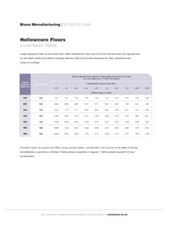
4 Recessing the sealant in the joint , or use of anopen-drained system, will minimise concentratedrainwater runoff and water-stain patterns. A nominal joint width of 20 mm will usually besatisfactory for most conditions and is therecommended design starting of most common types of joint between precastconcrete cladding and/or wall panels are: open-drained; face-sealed; and advantages and disadvantages are summarisedin Table jointDO NOT curtail vertical dummyjoint as this will lead to stainingDO NOT stagger vertical(or horizontal) Joints as thisleads to staining and stresson some cases it can lead tostress on the panel withpossible cracking of thepanelAVOID this configuration as itcan lead to potential waterstaining and leakage problemsVertical jointbetween panelsVertical jointbetween panelsFigure 1 Location of Joints Ta ble 1 Advantages and Disadvantages of joint TypesJoint TypeAdvantagesDisadvantagesOpen-drainedC an tolerate relatively large rear sealant is protected from UV lightand be installed from inside the building(no scaffold required).
5 Long maintenance-free for medium- and high-rise edges can have simple profile,no grooves be used for complex panel shapes(angled or curved).Can have a rear seal as a second line of first be readily inspected, repaired or for low-rise and quick to edges can be plain or simple supervision is required during installation as itis difficult to remedy defects due to poor suitable for tall vertical panels (> m in height).Cannot accommodate joint gap tolerances > 5 be applied from external scaffolding or other formof is exposed to UV light and weather needs more a single-seal system even a small failure may allowwater penetration due to capillary effects and be fully weatherproof, so limited to low-riseindustrial width is compression on seal at intersection ofhorizontal and vertical Joints is to maintain and/or while 1 Joints in Precast Concrete jointsThe open-drained joint is recommended for consists of a rain barrier in the formof an expansion chamber with a loose-fitting baffleand an air-seal at the interior face of the panel (seeFigure 2).
6 The baffle prevents direct entry of the wind-drivenrainwater. The pressure in the chamber between thebaffle and the internal air seal is at external airpressure. There is, therefore, no pressure differentialto drive rain past the baffle. The air-seal is thedemarcation barrier between outside and internal that enters the joint in front of the baffle isdrained downwards. At every intersection betweenthe vertical and horizontal Joints , a short length offlashing (300 mm) is used to ensure water isdischarged to the 2 Design and Construction of Open-Drained JointsInstall neoprene baffle strip after erection of next level of lapping detail on right for treatment at horizontal Joints Top baffleBottom bafflelapped underflashingAir-sealMinimum20 Minimum20 Horizontal air-seal Air-seal may be asealant with backing rod,closed-cell sponge orsquare neoprene stripVertical air-seal FlashingDrainage zone, 50 mm minimum300 Upstand*Minimum 120 Preferred 150* 50 mm typical.
7 75 mm in exposedlocationsFix flashing in placewith flexible seal under back and sidesOpen-Drained Joints are the RecommendedType for most Medium- to Joints can Tolerate LargeMovements and the Rear Sealant is Protectedfrom UV Light Open-Drained Joints can be Installed fromInside the 1 Joints in Precast Concrete jointsThese Joints are simple, economical and are mostsuited to low-rise construction(see Figure 3). Theyare sealed by a single run of gun-applied sealant closeto the exterior surface of the joint . A backing-rodforms the rear of the sealant. The external face sealshould, where practical, be supplemented by a sealnear the inside face of the jointsThis type of joint utilises a compressible impregnatedpolyethylene or polyurethane foam strip ispre-compressed and inserted into the joint after thepanels are erected or it is glued in position beforeplacement of the second panel,Figure thenexpands to fill the use of this type of joint seal is usually limited tolow-rise buildingssuch as factories and warehouseswhere wind pressures are low.
8 It can be used wherespandrel beams, downturns or columns restrict theaccess required for placement of gun-applied wall jointsHollowcore wall units are primarily used on low-risecommercial and industrial buildings. The jointsbetween panels are normally 10 mm wide and aresealed with a two-part polyurethane sealant placedagainst a closed-cell backing 4 Compression-seal JointsAABBVERTICAL FORMATSECTION A-ASECTION B-BHORIZONTAL FORMATC ompression seals gluedto edge of one panelFigure 3 Face-Sealed JointsMinimum 15 Preferred 20 Maximum 30 Minimum 15 Preferred 20 Maximum 30 Sealant withbacking-rodSealant withbacking-rodRear sealant optionalRearsealantoptional505 PPN 1 Joints in Precast Concrete Buildings4 joint choice of sealant and its specification, should bediscussed with sealant to be considered by the designer whenchoosing a suitable sealant material include.
9 The sealant should be impermeable to water. It should have a low elastic modulus toaccommodate strain due to joint movementwithout significant stress, with the shape of thesealant influencing the stress in the sealant. It should be able to recover its original shape aftercyclic deformation. It must bond firmly to the joint face without failingin adhesion nor splitting or peeling under theanticipated joint movements. It must not soften or flow at higher servicetemperatures and should not harden and becomebrittle at low temperatures. It should not be adversely affected by ageing orweathering and should be stable when exposed toUV light. For face-sealed Joints the sealant should have astable colour, be non-staining and resistant topickup of typesField-moulded sealants are available in the followingtypes: Polysulphide sealants (two-part) Polyurethane sealants (one- or two-part) Acrylic sealants Butyl sealants Silicone , silicone sealants should be avoided wherepossible as they stain the concrete surface andcannot be design and sealant applicationTo ensure the joint and sealant give satisfactoryperformance, the following points should be noted(see also Figure 5).
10 Correct joint preparation Correct sealant-backing systems Correct joint geometry Sufficient curing Rating of JointsExternal cladding may be required to have a specifiedFire Resistance Level (FRL). Cladding panels willusually be designed or tested to meet theserequirements in accordance with Section 5 ofAS sealant manufacturers produce sealants that aredesigned to provide resistance to fire. The jointdetails and sealants should be designed and applied inaccordance with the manufacturer s recommen-dations to give the required level of fire width/depth profileConcave sealant surfaceWidth greater than depthSealant too deepNo backup rodPoor geometry for movementChamfers set sealant backand protect concreteConcrete arrises subject tohandling damageCorrect joint DesignIncorrect joint Design12 x 12chamferstypical20 typicalFigure 5 joint Design Principles 2003 National Precast Concrete Association AustraliaDesigned and produced by TECHMEDIA P