Transcription of K(B)FD/TG4V-5, 12 Series Proportional Directional …
1 Proportional Directional valves with FeedbackK(B)FD/TG4V-5, 12 SeriesPressures to 315 bar (4500 psi)2 eaton Proportional valves KBFD/TG4V-5 V-VLPO-MC008-E2 November 2017 Section View ..03 Model Code ..04 Spool Data ..05 Fuctional Symbols ..05 OPERATING DATAV alves with Amplifier, KBFD/TG4V-5 ..06 valves without Amplifier, KFD/TG4V-5 .. 07 KBFD/TG4V-5 & KFD/TG4V-5 ..07 Pressures and Flow Rates ..07 PERFORMANCE CURVESP ower Capacity Envelopes, Single Solenoid Models ..08 Power Capacity Envelopes, Double Solenoid Models ..08 Flow Gain Curves ..09 Frequency Response ..09 INSTALLATION DIMENSIONSKFDG4V-5 ..10 KFTG4V-5 ..10 KBFDG4V-5 ..11 KBFTG4V-5 ..11 SUBPLATES AND MOUNTING SURFACESG eneral Description ..12 Mounting surfaces to ISO 4401 (Size 05) ..13 ELECTRICAL INFORMATIONB lock Diagram Voltage Input (M1) KBFDG4V-5 ..14 Block Diagram Current Input (M2)KBFDG4V-5 ..15 Wiring Connections Voltage Input(M1).
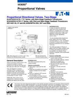
2 16 Wiring Connections Current Input(M2) ..17 APPLICATION DATAT able of contents This product has been designed and tested to meet specific standards outlined in the European Electromagnetic Compatibility Directive (EMC) 2014/30/EU which repealed Directive 89/336/EEC, amended by Directives 91/263/EEC, 92/31/EEC, 93/68/EEC and 93/97/EEC . For instructions on installation requirements to achieve effective protection levels, see the leaflet and Installation Wiring Practices for eaton s Electronic Products leaflet 2468 . Wiring practices relevant to this Directive are indicated by Electromagnetic Compatibility (EMC) .3 eaton Proportional valves KBFD/TG4V-5 V-VLPO-MC008-E2 November 2017 section viewKBFD/TG4V-5-*PE7, 1* DesignEaton vickers K(B)FD/TG4V Proportional valves are designed to provide a controlled oil flow in direct proportion to a command signal. They are available in two types; a double solenoid version that will provide reversible flow to an actuator and a single solenoid throttle version that provides a single direction of flow.
3 Hydrostats are available for load compensation and parallel flow path modules are available that will boost the flow capacity of single solenoid throttle versions to nearly twice that of the standard , both of these valve types can be supplied with or without an integral amplifier built directly onto the descriptionKBFD/TG4V-5A range of Proportional Directional and throttle valves with integral control electronics . Factory-set adjustments of gain, spool deadband compensation and offset ensure consistent repeatability valve-to-valve .The only electrical inputs required are power supply (24V) and a voltage command signal of 10V or 4-20 mA . The amplifier is housed in a robust metal enclosure, sealed against ingress of water and other fluids . Electrical connections are via a standard 7-pin plug .A spool position monitor pin allows the function of the valve to be electrically monitored . Ramp functions, if required, can be generated externally.
4 Features and benefits Factory-sealed adjustments ensure valve-to-valve reproducibility . Installation wiring reduced and simplified . Standard 7-pin connector . Standard 24V DC supply with wide tolerance band . Optional 10V DC or 4-20 mA command signals . Valve with integrated amplifier selected, ordered, delivered and installed as one performance-tested package . Spool position monitor pin to help with troubleshooting . Simple valve removal and replacement for service (plug & play) . Vibration and shock tested . Auxiliary DIN rail mounted electronic function modules available . Full CE electromagnetic compatibility . Full CE electromagnetic compatibility .- 2014/30/EU IP65 & IP67 valve environmental protection rating . Optional valve enable function .KFD/TG4V-5 This version is supplied without the integral amplifier .Features and benefits Wide range of spool and flow rate options . Electronic feedback LVDT ensures accurate spool position control.
5 Vibration and shock tested . Supported by a broad range of amplifiers and auxiliary function modules . Full CE electromagnetic compatibility .4 eaton Proportional valves KBFD/TG4V-5 V-VLPO-MC008-E2 November 2017 (B)9**3F10*4*11**15(V)5G12*16-(M)-6413** 17(U1)7V14-Z-18(**)19-H-201221EN**1 Valve typeKProportional valve2 Integral amplifierBIntegral amplifier B Series . Omit for models without integral amplifier3 Feedback arrangementFSpool position4 Control typeDDirectional valveTThrottle valve5 MountingGSubplate mounted6 Operation4 Solenoid operation7 Pressure ratingV315 bar (4500 psi) on ports P, A & B8 Interface5 ISO 4401, size 05-04-0-05 ANSI/B93 .7M-D05 . ISO 4401, size 05-06-0-05 (with L ports)9 102C - All ports closed at center, KBD11 122C30N30 L/min symmetric, meter in/ meter out2C50N50 L/min symmetric, meter in/ meter out2C65S65 L/min meter out only2C70N70 L/min symmetric, meter in/ meter out2C50N2550 L/min /25 L/min , meter in/ meter out2C75N4575 L/min /45 L/min , meter in/ meter out33C P closed at center, A,B,T connected, KBD33C30N30L/min symmetric, meter in/ meter out33C50N50 L/min symmetric, meter in/ meter out33C70N70 L/min symmetric, meter in/ meter out33C50N2550 L/min /25 L/min , meter in/ meter out9C zero lap9C50N50 L/min symmetric, meter in/ meter out2B single solenoid throttle valves , KBT2B30N30 L/min symmetric, meter in/ meter out2B50N50 L/min symmetric, meter in/ meter out2B65S65 L/min meter out only2B70N70 L/min symmetric, meter in/ meter out13 Flow rating ( B port flow for asymmetric spools) K(B)
6 FDG valves only2525 L/min (6 .6 USgpm) (50N25 only)4545 L/min (11 .9 USgpm) (50N25 only)Omit for symmetrical spools14 Manual OverridesZNo manual overrides15 Solenoids energization identity(Non-integral amplifier types KF only, omit for valves with integral amplifier)VSolenoid A is at port A end and Solenoid B is at port B end independent of spool typeBlank US ANSI B93 .9 standard (energize solenoid A , flow symbol is (P-->A)16 Command input(omit for valves with integral amplifier)M1+/-10V command and +/-10V feedbackM24-20mA command and +/-10V feedbackM3+/-10V command and 4-20mA feedbackM44-20mA command and 4-20mA feedback17 Solenoid connector(omit for valves with integral amplifier KBF)U1 ISO 4400/DIN 43650, non-integral amplifier type KF only (mating plug supplied)18 Electrical connection (KBF valves only)PE77-pin electrical plug with mating halfPH7As PE7 but with pin C used for enable signal19 Coil ratingH24 VDC amplifier supply20 Port T pressure limit code6 For 2C**S spools7 For all other spools21 Design number 12 seriesSubject to change22EN090 Resin filled,20 GEN119 Polyurethane interface sealsModel codes WARNING valves with integral amplifier are supplied with or without the metal 7-pin plug.)
7 The eaton plug, part no. 934939, must be correctly fitted to ensure that the EMC rating and IP67 rating are archieved. The plug retaining nut must be tightened with a torque of Nm ( lbf ft) to effect a proper a proper : Additional configurations available upon request . Please contact you customer sales representative for details .5 eaton Proportional valves KBFD/TG4V-5 V-VLPO-MC008-E2 November 2017 symbolsAvailable spools for K(B)FDG4V-3 Spool type 9C**N, meter-in/meter-outSpool type 2C**N, meter-in/meter-out (zero lap)Spool type 2C**S, meter-out onlySpool 33C**N, meter-in/ meter-outSpool type and flow ratingSymmetric spoolsBase line starting at p = 5 bar (75 psi) per metering flow pat, e .g . B to T . For actual maximum flow refer to power capacity envelope curves .Spool code spool symbol flow rating Spool codeSpool symbolFlow rating2C30N2C30 L/min ( USgpm)2C50N2C50 L/min ( USgpm)2C65S2C65 L/min ( USgpm)2C70N2C70 L/min ( USgpm)9C50N9C50 L/min ( USgpm)33C30N33C30 L/min ( USgpm)33C50N33C50 L/min ( USgpm)33C70N33C70 L/min ( USgpm)Spool code spool symbol flow rating Spool codeSpool symbolFlow rating2B30N2B30 L/min ( USgpm)2B50N2B50 L/min ( USgpm)2B65S2B65 L/min ( USgpm)2B70N2B70 L/min ( USgpm)Spool code spool symbol flow rating Spool codeSpool symbolFlow rating2C50N252C 50 L/min ( USgpm), A port flow25 L/min ( USgpm), B port flow2C75N452C 75 L/min ( USgpm), A port flow45 L/min ( USgpm), B port flow33C50N2533C 50 L/min ( USgpm), A port flow25 L/min ( USgpm), B port flowFor K(B)FDG4V-5 valvesFor K(B)FTG4V-5 valvesFor K(B)FDG4V-5 valvesAsymmetric spoolsFigure preceding metering type designator, N (e.)
8 G . 2C**N) is flow rating P A, or A T ( A port flow); figure after N (N**) is flow rating P B, or B T ( B port flow) .Available spools for K(B)FTG4V-5 Spool type 2B**N, meter-in/meter-outFunctional symbolsModel types KBFDG4V-5 Proportional Directional valve (with intergated electronics)Model types KBFTG4V-5 Proportional throttle valve (with intergated electronics)Model types KFTG4V-5 Proportional throttle valve (requires amplifier card)Model types KFDG4V-5 Proportional Directional valve (requires amplifier card)PTBAL7-pinplugPTBALPTBLAPTBALS pool data6 eaton Proportional valves KBFD/TG4V-5 V-VLPO-MC008-E2 November 2017 is typical with fluid at 36 cSt (168 SUS) and 50 C (122 F).Power supply24V DC (18 V to 36V including 10% peak-to-peak max. ripple) max current 3 ACommand signalVoltage mode M10 to +10V DC, or 0 to -10V DC, or -10V to +10V DC Input impedance47kohms Common mode voltage to pin B18V (max)Current mode M24-20 mA Input impedance100 Max differential voltage to Pin E to Pin B 100mV10V Valve enable signal for model codes PH7 Enable> (36V max)Disable< VInput impedance10 k ohms7-pin plug connectorPin DescriptionFAGBCDEA Power supply positive (+)B Power supply 0VC Not connected (PE7)C Valve enable (PH7)D Command signal (+V or current IN)E Command signal ( V or current GND)F Output monitorG Protective groundElectromagnetic compatibility (EMC)Conducted Emissions CISPR11 -2015-06 Ed - Class A, 150kHz to 30 MHzRadiated Emissions CISPR11 -2015-06 Ed /EN55011 - Class A, 30 MHz 1 GHzRF Continuous conducted disturbances IEC 61000-4-6, Class A 150 KHz to 80 MHz DC Power Port.
9 10 Vrms Signal/Control Port : 10 VrmsRF Electromagnetic field, 80 MHz to 2700 MHz, 10V/m, Meets criterion ASurge: IEC 61000-4-5 DC power port : 1kV Signal/control port : 1kVElectrical Fast Transients IEC 61000-4-4, Class B DC power port : 2kV Signal/control port : 1kVElectrostatic discharges (ESD) IEC 61000-4-2, Class B Air 8kV, Contact 4kVThreshold command voltage (minimum voltage for minimum flow) signal (pin F)KBFD valves 10V DC for full spool strokeKBFT valves0 to 10 V DC for full spool strokeVoltage mode +/- 10V DC for full strokeOutput impedance10 KOhmCurrent mode 4mA to 20mAOutput impedanceUpto 200 OhmPower stage PWM frequency10 kHz nominalStep input response with flow through P A B T p = 5 bar (75 psi) per metering path, P ARequired flow step:Time to reach 90% of required step:0 100%30 ms100% 040 ms+90 -90% (KBFDG4V3-3 only)32 msReproducibility, valve-to-valve (at factory settings): Flow at 100% command signal 5%KBFD/TG4V-5 valves with integral amplifierOperating dataK(B)FD/TG4V-5 valves with amplifier7 eaton Proportional valves KBFD/TG4V-5 V-VLPO-MC008-E2 November 2017 is typical with fluid at 36 cSt (168 SUS) and 50 C (122 F).
10 Max current, at 50 C (122 F) ACoil reistance, at 20 C (68 F) Step responseStep size (% of max spool stroke)Time to reach 90% of required step:0 to 100%31 ms100% to 030 ms+90 to -90% (KFDG4V-5 only)45 msType of protection, with electrical plugs fitted correctlyIEC 60529, Class IP65 Electromagnetic compatibility (EMC)Emmision (10V/m)EN 50081-2 Immunity (10V/m)EN 50082-2 Maximum allowable ambient air temperature60 C (140 F)Maximum allowable oil temperature60 C (140 F)Supporting products:Eurocard amplifiersEEA PAM 533 A/B/C/D/E/FSee catalog GB-2464 KFD/TG4V-5 and KBFD/TG4V-5 valves (all valves )Relative duty factorContinuous rating (ED = 100%)Hysteresis with flow through P A B T<1% of max stroke (center-to-offset)Mass: kg ( lb) : kg ( lb) : kg ( lb) : kg ( lb) test equipmentEBA TEQ 460 A 10 See catalog V-ELAC-TM001-EModelPort L conditionPorts P, A, BTTAll models for normal usage (L port not connected)Normally blocked by mounting surface315 (4500)160 (2300)160 (2300)For K(B)FDG4V-5**C**N-Z models only a higher T port pressure is allowed if the L port is connected directly to tankDrained directly to tank315 (4500)210 (3000)210 (3000)KBFD/TG4V-5 valves without Integral Amplifier (requires a Eurocard Amplifier, refer to supporting products)Operating dataKFD/TG4V-5 valves without amplifierPressure and flow ratesMaximum pressures, bar (psi)ProtectionElectricalReverse polarity protectedEnvironmentalIEC 60529, Class IP65 & IP67 ROHS complianceElectronic amplifier is compliant to 2011/65/EU ROHS2 Ambient air temperature range for full performance-40 C to +85 C (-40 F to 185 F)