Transcription of KEYSTONE FIGURES 310/312 K-LOK BUTTERFLY VALVES
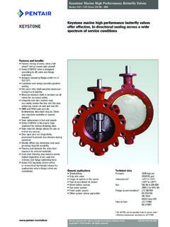
1 KEYSTONE FIGURES 310/312 K-LOK BUTTERFLY VALVES 2017 Emerson. All Rights - Wafer high performance BUTTERFLY valve312 - Lugged high performance BUTTERFLY valveVCTDS-02876-US 17/01 FEATURES Uninterrupted gasket surfaces help eliminate problems associated with seat retaining screws in the gasket surface and allows use of standard spiral wound gaskets. Unique interference seat design with energized elastomer O-ring allows bi-directional ANSI Class VI shut-off at lower pressures. The seat is further energized by line pressure, providing the same tight bi-directional shut-off at full-rated pressure. Heavy duty circular key holds the seat and retaining ring in place, providing bi-directional, dead-end service at full-rated pressure. This helps eliminate the need for easily corroded and hard-to-remove retention screws. Valve stem designed to API 609 standards is blow-out resistant.
2 Seat retaining ring is housed within the flange gasket ID to eliminate potential emission path. Face-to-face conforms to MSS SP-68 and can be configured to ISO 5752 short. Adjustable packing utilizes unique rocker-shaped gland bridge that compensates for uneven adjustment of gland nuts. Extended neck allows for two inches of clearance for DATASize range: NPS 2 to 12 (DN 50 to 300)Rating: ASME Class 150 Pressure: 285 psi ( bar) bi-directional, dead-endVacuum: 50 micronsTemperature: -20 F to 350 F (-29 C to 177 C)GENERAL APPLICATIONHigh performance applications such as steam, chill water, water, utility lines, gasoline, natural gas, air, oil, jet fuels and process lines. Contact your sales representative for appropriate materials for specific complianceASME 609 MSS-SP68 CRN RegistrationPED Compliant in some FIGURES 310/312 K-LOK BUTTERFLY standardOptional material1 Stem17-4 PHASTM A 564 cond.
3 H1075 or H 1100316 SS cond. B2 Disc316 SSASTM A 351-CF8M3 Gland bridge17-4SS HTASTM A747-CB7C1-14 Packing gland follower316 SSASTM A 276-3165 Blowout-resistant ring18-8 SS6 PackingTFEDie formed TFE braidGraphite7 Anti-extrusion ring316 SSASTM A 276-3168 Bearings (upper and lower)CSTFE impregnated/fiber reinforcedSSTFE impregnated/fiber reinforced9 BodyCSASTM A216-WCBSSASTM A351-CF8M10 Seat retaining ringCSASTM A36 SSASTM A24011 SeatRTFER einforced polytetrafluoroethylenePTFE12 Wedge pins17-4 PHASTM A564316 SS cond. B13 Seat backing O-ringPFA encapsulated FKM14 Circular key304 SSASTM A24015 Thrust bearing (upper and lower)316 SSNitridedUPPER STEM DESIGN3 KEYSTONE FIGURES 310/312 K-LOK BUTTERFLY VALVESFull OpenLinear CharacteristicFlow Coefficient (Cv)Equalinear CharacteristicEqual Percentage CharacteristicDESIGN FEATURESStem (1) is manufactured from materials that provide maximum strength and stability.
4 The stem surface is finished to better than Ra 31 for maximum sealing interface between the stem and the bridge (3) incorporates a rocker shape to compensate for uneven adjustment of the gland nuts. The upper gland nuts are captured in the bridge for ease of gland follower (4) has a circular groove for easy field ring (5) is standard on all Figure 310 and 312 (6) utilizes a combination of force-dried, soft-braided rings and solid TFE V rings to provide a superior stem (8) of press fit steel or stainless steel are located near the disc to minimize the possibility of (9) features an extended neck that allows for two inches of insulation and integral cast travel stop. Non-interrupted flange gasket surfaces allow for the use of standard spiral wound retaining ring (10) is located within the flange gasket ID. This allows for an uninterrupted flange sealing surface and maximum emissions (11) is an advanced patented bi-directional dual-lock seat design* that provides an interference disc/seat seal at vacuum-to-low pressures and utilizes line pressure to achieve maximum sealability at medium-to-high pins (12) are tangentially located for maximum strength and then welded in place after final assembly and backing O-ring (13) is available in a variety of materials to meet customer requirements.
5 (Materials and applications are listed on page 8.)Circular key (14) provides bi-directional, dead-end service at full-rated pressure. Removable in the field for quick seat cast mounting pad allows direct mounting of KEYSTONE location webs allow precise alignment of valve between pipe flanges during 50 microns to Low PressureMedium to High PressureSPECIFICATIONSP rinciples of designK-LOK is an ideal control valve designed to provide an inherent equalinear characteristic that is suitable for most linear and equal percentage applications. The valve offers a high flow capacity, thin profile disc with a rangeability of 33:1. The use of tangentially located disc/stem wedge pins removes engagement clearances and eliminates valve the valve is throttling, the stem s double offset location causes the disc to cam away from the seat, reducing wear and deformation.
6 When the disc closes, a drop tight seal is assured. (See page 4 for additional information.) *PatentedO-ring backing ring provides memory to polymer seatInterference between the disc and seat provides an ANSI Class VI shut-offCircular keySeat retaining ringSeatO-ring backing ring provides memory to polymer seatCircular keySeat retaining ringSeatLine pressure assists sealAngle Of Opening4 SPECIFICATIONSDISC AND SEAT DESIGNK-LOK disc geometry maximizes flow capacity by increasing the available flow area through the valve. This increase in disc efficiency results in a high valve stem vs. one-piece stemThe improved Cv may be easily explained by comparing the aspect ratio of the K-LOK two-piece stem and disc arrangement to that of a through-stem design. This unique disc configuration provides a universal inherent flow characteristic which is referred to as offset disc/stemThe K-LOK design uses a double offset disc/stem design.
7 The first offset is achieved by locating the stems downstream of the centerline of the seat. This allows for a total unobstructed 360 degrees sealing second offset locates the stems off the center of the vertical axis of the combination of these two offsets creates a camming effect as the disc swings into and out of the seat. The disc lifts quickly out of the seat in the first few degrees of travel and does not contact the seat again until it is nearly closed. There is minimum wear between the seat and disc, so operating torques are reduced and seat life is OFFSETDOUBLE OFFSETC ompetitor:with one-piece stemK-LOK :with two-piece stemAspect ratio = open area disc areaSECOND OFFSETKEYSTONE FIGURES 310/312 K-LOK BUTTERFLY VALVES530028525020015010050-200100200300 400500204142535424650522 0122647729512113714230143053821111421611 6841139791231832603474434965246613320229 5425574755859632851702553715387299681106 8361483024576771016142320342344104122145 5691103215712228327137811245288596907135 820822968440951022 BBG921011091181261351412 BAC1421581751912082242363 BAC1751952152352552742884 BAC2602963333694064424685 BAD3274114955796647488076 BAD448563677792906102111018 CAE5007601019127915391798198010 CAF67811191560200024412882319112 CAF970160422382873350741414585 KEYSTONE FIGURES 310/312 K-LOK BUTTERFLY VALVESCv VALVES VS.
8 TRAVEL POSITION (installed in the preferred flow direction)Angle of openingSize NPS10 20 30 40 50 60 70 80 90 PTFE AND RTFE BI-DIRECTIONAL SEATING AND UN-SEATING TORQUE VALUES (clean water service)Size NPSS haft mounting codeSeating and un-seating torque (lbs in)System shut-off pressure (psig)050100150200250285 SEATING AND UN-SEATING TORQUES eating and un-seating torques are a function of the size of the valve and the shut-off pressure of the torque ratings can be found in the seating/un-seating chart at the intersection of the size row and the shut-off pressure torques listed are for normal service conditions ( operating frequency is a minimum of once per month; disc corrosion is expected to be mild or minor, the media is a clean gas, liquid or steam, and is non-abrasive) and the chemical effects upon the seat are Torques are applicable to PTFE and RTFE For other service conditions, select the torque applicable for the maximum differential pressure and multiply by the following factor: Water: x Lubricious service: x Dry service: x Heavy solids.
9 X RATING FOR BODY AND BACKING RING MATERIALSSPECIFICATIONSP ressure (psig)Temperature, FCF8M Body ANSI 150 WCB Body ANSI 150 NitrileEPDMFEP Encapsulated FKMTMF luoroelastomer (FKM)6E N/AN/A3 47/168 BBG2 47 47 47 N/AN/A3 47 N/AN/A3 47 N/AN/A549 x 549 x 549/1699 CAF24 - UNC 4 52 4 - UNC 4 534 - UNC4 5 48 - UNC 4 5 58 - UNC 5668 - UNC 5 688 - UNC 5 6 1012 - UNC 6 7 1212 - UNC77 KEYSTONE FIGURES 310/312 K-LOK BUTTERFLY VALVESWAFER STYLE Size NPSV alve dimensionsTop plate drillingAdapt. codeMSSKeyBolt circleNo. (lbs.)ABCQEDFG HJDIMENSIONS WAFER STYLE310 WAFER RECOMMENDED FLANGE BOLT LENGTHSSize sizeLengths of fasteners (in.)BoltsAll-thread studsNOTEBolt lengths are based on ANSI Class 150 weld neck flanges per ANSI and a gasket thickness of - 11 UNC-2B43 47/1612 BBG2 - 11 UNC-2B43 47 - 11 UNC-2B43 47 - 11 UNC-2B83 47 - 10 UNC-2B83 47 - 10 UNC-2B83 47 - 10 UNC-2B8549 - 9 UNC-2B12549 - 9 UNC-2B12549/16159 CAF24 - UNC1 2 1 2 2 4 - UNC1 2 22 34 - UNC1 2 22 48 - UNC1 2 22 58 - UNC232 368 - UNC232 3 88 - UNC232 3 1012 - UNC2 3 2 3 1212 - UNC2 3 2 4 KEYSTONE FIGURES 310/312 K-LOK BUTTERFLY VALVESLUG STYLE Size NPSV alve dimensionsTapped lug dataTop plate dataWeight (lbs.)
10 Adapt. codeMSSBolt circleNo. holesHole LUG STYLE312 LUG RECOMMENDED FLANGE BOLT LENGTHSSize sizeLength of fasteners (in.)Up stream side - L1 Down stream side - L2 BoltsAll-thread studsBoltsAll-thread studsP tap on MBolt circle R holesNOTEBolt lengths are based on ANSI Class 150 weld neck flanges per ANSI and a gasket thickness of 300 YNYNYNYYYYYNYNYNYNDIN 2632 PN-10 YYYYYNYYYYYYYYYYYYDIN 2633 PN-16 YYYYYNYYYYYYYNYYYYDIN 2634 PN-25 YYYNYNYYYYYYYNYYYNJIS B 2212 10 KYYYYYNYYYYYYYNYYYNJIS B 2213 16 KYNYNYNYYYYYNYNYYYNKEYSTONE FIGURES 310/312 K-LOK BUTTERFLY VALVESOPTIONAL FLANGE STANDARDSS tandardSize (in.)22 3456810123103123103123103123103123103123 10312310312310312310312 OPTIONSNOTES1. Optional flange standard must be specified at time of Valve is rated to 285 psi. Do not exceed pressure VALVES & Emerson trademarks and logos are owned by Emerson.


