Transcription of Kick-Down or Straight-Acting Jacks With or Without Air …
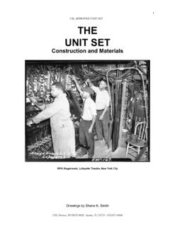
1 SERVICE MANUALML13514 Panel BI-AXIS ControlCentral GroundingFEATURING:HWH CORPORATION(On I-80, Exit 267 South)2096 Moscow Road | Moscow, Iowa 52760Ph: 800/321-3494 (or) 563/724-3396 | Fax: 563 SERIES LEVELING SYSTEMHWH TOUCH PANEL-CONTROLLEDWCORPORATIONHHRRKick-Dow n or Straight-Acting JacksRWith or Without Air DumpSECURELY BEFORE REMOVING TIRES OR CRAWLING UNDER OPERATOR S MANUAL BEFORE USING. BLOCK FRAME AND TIRESCAUTION!HWH HYDRAULIC LEVELINGLEVELOFFSTOREHYDPARK/BRAKEDUMPNO T INSECTION STEPSSECTION3 DIAGRAMSSECTION1 TROUBLESHOOTINGSTEPS3 PART FOLDERHOW TO USE MANUALPROCEED with TROUBLE SHOOTING GUIDEThis manual is written in three sections. Section 1 is the Trouble Shooting Steps. Section 2 is the Repair Steps. Section 3 isthe Diagrams. Begin diagnosis of the system with Section 1, the Trouble Shooting Steps. This will give the correct operationand function of the system. When a malfunction is encountered, the Trouble Shooting Steps will direct you to the proper RepairSteps in Section 2, the Repair Steps.
2 The Repair Steps are broken into 3 columns, Problem, Solution, and Diagram. In theproper part under Problems, find the symptom you have encountered. The testing and repair for that problem is in the Solu-tion (center) column. Diagrams for a particular Problem and Solution are in the Diagram (right hand) column. This column willdirect you to the proper diagram in Section 3, Diagrams, for a more detailed beginning your repair, it is IMPORTANT to read the CAUTIONS and NOTES AND CHECKS in the first section, TROUBLESHOOTING STEPS. In many cases this will save time and mistakes when trouble shooting a Repair Manual is offered as a guide only. It is impossible to anticipate every problem or combination of problems. Thismanual is written in sequential order of the proper operation of the system. The Trouble Shooting Steps must be followed inorder to give correct diagnosis of the problem(s). For any problems encountered that are not addressed in this manual, contactHWH Corporation for : Diagrams in this manual are of typical systems.
3 There may be plumbing or harness differences. In most casesthis should not effect trouble shooting AND CHECKSRead and check before proceeding with Trouble Shooting : HWH CORPORATION ASSUMES NO LIABILITYFOR DAMAGES OR INJURIES RESULTING FROM THEINSTALLATION OR REPAIR OF THIS If the Jacks cannot be retracted, see TROUBLE SHOOTING Step8 for temporary measures. Make sure the manual retractvalves are closed before trouble The Trouble Shooting Guide must be followed in order. Prob-lems checked for in one step are assumed correct and notchecked again in following Do not replace the control box unless the Repair Steps sayto replace it. Otherwise the malfunctions may damage thenew control Proper grounding of all components is critical. See the electricalcircuit for specific grounds required. Faulty grounds, especiallyfor the control box, solenoid manifold or the pump assembly,may cause control box component damage and /or improperor erratic manual is intended for use by experienced mechanicswith knowledge of hydraulic and automotive electricalsystems.
4 People with little or no experience with HWHleveling systems should contact HWH technical service(800-321-3494) before beginning. Special attention shouldbe given to all cautions, wiring, and hydraulic note: When installing a new control box, makesure the box is properly grounded before applying powerto the tools for trouble shooting the HWH leveling systems:JUMPER WIRES(UP TO 10 GAUGE)PRESSURE GAGE(3500 PSI MIN.)MULTI-METER12 VOLT TEST LIGHTPROCEED with THE TROUBLESHOOTING STEPS ON THEFOLLOWING PAGE3. Check that the oil reservoir is full with the Jacks in the fullyexisting hose end, tighten the hose end to snug plus 1/4tighten the hose end 1/3 turn (2 FLATS). If tightening anmake the hose end snug (finger tight) on the fitting, thenTightening of hose ends: If tightening a new hose end,turn (1 FLAT).will not supply enough power for the system to operate no weak cells. An alternator, converter or battery chargergood voltage under load. Batteries must be in good conditionunder no load should read volts.
5 Batteries must maintainthe coach batteries to supply power to the pump. Batteriespower for the control box and hydraulic pump. DO NOT useand the other(s) for the coach. The engine battery supplies4. Most coaches have more than one battery; one for the engineREAR WHEELS, THE VEHICLE MAY ROLL FORWARD OR BACKWARD OFF THE NOT OVER EXTEND THE REAR Jacks . IF THE WEIGHT OF THE VEHICLE IS REMOVED FROM ONE OR BOTHSAFETY CLASSES ARE TO BE WORN TO PROTECT EYES FROM DIRT, METAL CHIPS, OIL LEAKS, ECT. FOLLOWNEVER PLACE HAND OR OTHER PARTS OF THE BODY NEAR HYDRAULIC LEAKS. OIL MAY CUT AND THE Jacks MAY ABRUPTLY SWING UP WHEN THE FOOT CLEARS THE GROUND OR WHEN THE jack REACHESEXHAUST OR ANY HIGH TEMPERATURE COMPONENTS OF THE ROUTING OR REROUTING HYDRAULIC HOSES AND WIRES, BE SURE THEY ARE NOT EXPOSED TO ENGINEMAY DROP AND OR MOVE FORWARD OR BACKWARD Without WARNING CAUSING INJURY OR OR AIR SUSPENSION TO SUPPORT VEHICLE WHILE UNDER VEHICLE OR CHANGING TIRES. VEHICLEBLOCK FRAME AND TIRES SECURELY BEFORE CRAWLING UNDER VEHICLE.
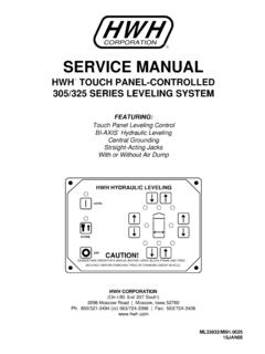
6 DO NOT USE THE LEVELINGWARNING!ALL OTHER SHOP SAFETY THE SKIN CAUSING INJURY OR SHOOTING "ON" BUTTON"OFF" BUTTONON LIGHTWARNING LIGHTS(4-Red)LEVELING LIGHTS(4-Yellow)CAUTION!ONSTOREOFFHWH HYDRAULIC LEVELINGUNDERSTAND OPERATOR S MANUAL BEFORE USING. BLOCK FRAME AND TIRESSECURELY BEFORE REMOVING TIRES OR CRAWLING UNDER VEHICLE."DUMP"EXTEND FRONT BUTTONRETRACT FRONT BUTTONRETRACT RIGHTSIDE BUTTONEXTEND RIGHT SIDE BUTTONPARK/NOT INBRAKEEXTEND REAR RETRACT REAR BUTTONSTORE LIGHTDUMP"STORE"1. Make sure the transmission is in the recommended positionfor parking and the park brake is set. with the ignition switchoff, there should be no power to the leveling system. If anytouch panel lights are on or the pump is running, see Part 1 of the Repair Turn the ignition switch to "ON". The touch panel shouldremain off. If this is not so, see Part 2 of the Repair Turn the ignition to the "ACC" position. Push the "ON" (I)button. The red POWER ON light should glow steady.
7 Oneyellow LEVELING light may be on. No other lights should beon. The pump should not run. If this is not so, see Part 3 ofthe Repair Jacks operate in pairs, front, sides or rear. The up arrowsare EXTEND buttons, and down arrows are RETRACT (EXTEND buttons) to kick the Jacks following the vehicle has Kick-Down Jacks , use the front and rear upNOTE:ground before the other jack moves to the vertical is ok as long as the first jack does not lift the vehicle aftertouching the Push the front, then the rear EXTEND buttons to kick thejacks vertical or extend Straight-Acting Jacks . The pump willcome on, the Jacks will kick vertical or extend, the individualred WARNING light for each jack will come on and the pumpwill shut off as the button is released. Kick-Down Jacks shouldremain in the vertical position. If any of this does not happen,see Part 4 of the Repair Air dump Level sensing unit the Jacks to the groundand put the coach in a level position.
8 All yellow lights shouldbe out. If a yellow light is on, adjust the sensing unit. Checkthat the sensing unit is positioned properly and mounted to asolid surface. If the sensing unit cannot be adjusted, yellowlights never come on or more than one yellow light comes onat a time, see Part 6 of the Repair is assumed at this point the system will level the coach prop-erly and the level sensing unit is set. It is also assumed the red warning lights and yellow level lights are working the vehicle has Straight-Acting Jacks , use any up arrows forAs jack pairs kick vertical, one jack may extend to the7. Turn the touch panel on. Push the "STORE" button. Thered STORE light should come on. All four Jacks will start toretract. Kick-Down Jacks will fold up when the foot of the jackclears the ground. When a Kick-Down jack is horizontal, thered warning light for that jack will go out. When a straight -act-ing jack is extended less than 2 inches, it s red warning lightwill go foot of the jack should continue to retract completely intothe cylinder.
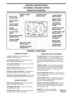
9 Two minutes after all the red lights go out, thesystem will shut off. If any of this does not happen, see Part7 of the Repair "DUMP" button is a momentary but-ton. The "DUMP" button will only work with the panel on. Pushand hold the "DUMP" button. the air should exhaust from thevehicle s suspension. Release the "DUMP" button. The ve-hicle should return to the proper ride height. If any of this doesnot happen, see Part 5 of the Repair LEFT BUTTON"NOT IN PARK" LIGHTRETRACT LEFT SIDE BUTTON8. Emergency jack solenoid valve is equip-ped with a "T" handle release valve. Turn the handle counterclockwise approximately 3 turns or until the Jacks start to re-tract. The oil will return to the reservoir and the jack should re-tract. After all the Jacks are full retracted, turn the "T" handlesclockwise until snug. See Part 8 of the Repair CORPORATION2096 MOSCOW BOX 0183 MOSCOW, IOWA 52760-0183800-321-3494319-724-3396ML1351 4 SYSTEMSFEATURING:HWH TOUCH PANEL - CONTROLLEDTOUCH PANEL BI - AXIS CONTROLKICK - down JACKSBEGIN with SECTION 1 SECTION 2 straight - acting JACKSREPAIR MANUAL310 SERIESINTERNET: http: 1 There should be no +12 power to the control box.
10 Trace the (BROWN)Release the park brake. If the pump stops, replace the control the pump continues to run, replace the pump 2 with the ignition switch in the "ON"position:a. The touch panelhas indicator The master "JACKSDOWN" warninglight and/or buzzeris on. (The jacksshould all be in thestore position.)Push the "OFF" button on the touch panel. The ON light should goout. If the lights come back on when the "OFF" button is released,replace the touch the "ON" (I) button one time. A red WARNING light on thetouch panel should come on indicating a jack is Touch panel hasindicator lights onwith the ignitionswitch The pump is run-ning TO TO TO AMP10 AMP10 AMP10 AMP5 AMPCAUTION!ONSTOREOFFHWH HYDRAULIC LEVELINGUNDERSTAND OPERATOR S MANUAL BEFORE USING. BLOCK FRAME AND TIRESSECURELY BEFORE REMOVING TIRES OR CRAWLING UNDER INBRAKEDUMPABTOUCHPANELRFWith the ignition offand the park wire in the 3 pin UML connector to its source. The wire should beconnected to the accessory side of the ignition switch.