Transcription of Kid-powered squaris wheel - Vintage Projects and Building ...
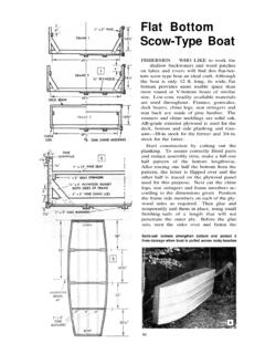
1 Kid-powered & quot ; squaris & quot ; wheelDESIGNED By ROBERT WOOLSONPREPARED By W. CLYDE LAMMEYDUBBED A & quot ; squaris wheel & quot ; by its designerbecause of its square wheel , this pint-sized back-yard version of its big brother, the ferris wheel ,will bring safe carnival fun right to your to make it as sturdy as possible, thewheel is designed to operate on & quot ;kid power.& quot ;That is, each time around, each passenger givesthe wheel a backward push with his feet. Therethat can be fun for up to eight totsIf you'd like to start a carnival in your own yard,here's an unusual rideThe shafts on which the balanced bucket seats pivot also serve as safetybars.
2 The mending plates on the side panels save wear at the shaft holesis no danger of traveling too fast for safety, andno danger of falling out of the bucket seats, sincethe small riders are held in by a safety safety feature is a set of wheel locks,which prevent the toy from being used whenmom or dad can't be around to supervise gettingon and getting a first step in construction, carefully lookover the pull-apart drawing on page 968. Notethat many of the individual assemblies are de-tailed in the drawing on page 969.
3 If you followthese details with care, the assembly will not bedifficult. One word of caution: The base, theA-frames and the wheel spider are made of2 x 4s. It is very important that you obtain clear,straight stock for these parts. There must be noknots, no weakening blemishes and no crookedpieces, as otherwise you may have trouble build-ing and operating the must run trueThe wheel must run true after assembly, andA-frames must stand plumb with the baseleveled. The stand, which consists of the baseand A-frame, must be set up and leveled on asolid foundation, made either by pouring acouple of narrow concrete slabs on a tamped-gravel fill or two rows of concrete blocks placedon a tamped gravel fill.
4 Then you level the struc-ture by shimming up the low corners. Woodenshingles are just the thing for shimming. Al-though standard 2 x 4s are held to quite closesectional sizes, you may occasionally find somevariations in widths and thicknesses. Usually it'sa good idea to check before cutting stock as anyappreciable variation might affect some of thedimensions glue in assemblyAfter you have a proper foundation, make thebase, which consists of two lengthwise membersand three cross members, the latter mortised thefull thickness into the lengthwise members andjoined with bolts.
5 No glue is used in the entireassembly; only bolts and lagscrews. Next, youmake the A-frames, joining at the top ends firstas shown in one of the pulled-apart assemblies onpage 969. When cutting the top ends of theA-frame members, or legs, lay out according tothe detail and saw outside the line in the permits planing the cut surface to a smoothfit against the hole pattern on the inside and outsideplywood gussets is identical except for the upper1/4i-in. hole in each outside gusset. This hole takesPivoted wheel locks are provided as a safeguard toprevent use when no adults are presentthe bent end of the pin, the lower end of whichpasses through a cross hole drilled near eachend of the wheel shaft, preventing the latter fromturning or working out of place.
6 The shaft holesin both inside and outside gussets should becarefully located, but location of the bolt holesis not critical; just locate them uniform distancesfrom the assure register of all bolt and shaft holes,drill the shaft holes first through both gussetsand the filler piece, then insert the shaft, clampthe parts together and drill through all threethicknesses. Remember to check beforehand thediameter of the pipe which is used as a the top ends of the A-frames joined, boltthe legs to the base, plumb with a level and bracetemporarily until you can install the permanentbraces.
7 The lower ends of the latter are joinedto the center cross member of the base with lag-screws, the washered heads seating in pocketscut into the wide face of the brace with a chiseland gouge as indicated in the assembly view, carriage-bolt heads at the top ends of thebraces are seated in shallow counterbores, thelarge diameter of the latter being slightly largerthan the bolt head. Tighten the bolts before re-leasing the temporary braces. Then check againfor , make the wheel spiders, noting that inthe pulled-apart view on page 969 each consists968of three members joined at the center to a ply-wood gusset, making four equally spaced spokesof equal length.
8 Note also that there is a spacerbetween each wheel gusset and the inside gussetat the top end of each A-frame. These spacerscan be band-sawed round as detailed or theycan be squares center-drilled to a free fit on thewheel the wheel spiders on the shaft withthe spacers in position, making sure that bothturn freely. Then locate and drill the holes forthe lagscrews which hold the four spreaders asin the detail, D. It's important to cut the ends ofthe spreaders square and all pieces to exactlength. Drill a 1/4-in.
9 Hole edgewise near the endof each spoke, insert and tighten a carriagebolt in each of the holes to prevent the spokeends from splitting. Then drill the 5/8-in. holes inthe spokes for the shafts on which the seats 1x2 wheel -spider braces are installed of the seats, sizes of the parts andthe method of pivoting each seat are shown indetail. Cut four bottoms and four backs to thesizes given from 1/2-in. plywood, then eight endpieces from 3/4-in. plywood to the size all cut edges with sandpaper and thenround them slightly.
10 Be sure there are no note that the backs and bottoms are butt-joined to the ends with steel inside & quot ;corner irons& quot ;as they are often referred to, nine corners beingrequired for each seat. The ninth corner is at-tached to the bottom and back at the center ofthe seat. Precise spacing of the corners at theends is not important; just equalize the plate bearingsThe method of pivoting the seats is shown inthe assembly, E. Spacers and two washers areplaced between the ends of the seat and thewheel spokes as indicated. The shaft on whicheach seat pivots is held in place by shaft collars,one at each end.