Transcription of Kinetix VP Low Inertia Servo Motors Installation Instructions
1 Installation InstructionsOriginal InstructionsKinetix VP Low Inertia Servo Motors with mm Frame SizeCatalog Numbers VPL-A0631, VPL-A0632, VPL-A0633, VPL-A0751, VPL-A0752, VPL-A0753, VPL-A1001, VPL-A1002, VPL-A1003, VPL-A1152, VPL-A1153, VPL-A1303, VPL-A1304, VPL-A1306, VPL-B0631, VPL-B0632, VPL-B0633, VPL-B0751, VPL-B0752, VPL-B0753, VPL-B1001, VPL-B1002, VPL-B1003, VPL-B1152, VPL-B1153, VPL-B1303, VPL-B1304, VPL-B1306, VPL-B1651, VPL-B1652, VPL-B1653, VPL-B1654 Summary of ChangesThis publication contains new and updated information as indicated in the following the Kinetix VP Low Inertia MotorsKinetix VP low- Inertia Motors feature single-turn or multi-turn high-resolution absolute encoders, and are available with or without 24V DC brakes. These compact brushless Servo Motors meet the demanding requirements of high-performance motion systems. You are responsible for inspecting the equipment before accepting the shipment from the freight company. Check the items you receive against your purchase order.
2 Notify the carrier of shipping damage or missing items immediately. Store or operate your motor in a clean and dry location within the Environmental Specifications on page Page Topic Page Summary of Changes 1 Motor Dimensions ( mm frame sizes) 8 About the Kinetix VP Low Inertia Motors 1 Connector Data 10 Catalog Number Explanation2 Load Force Ratings 11 Before You Install the Motor 2 Environmental Specifications 22 Functional Safety 4 Motor Accessories 22 Motor Installation 5 Additional Resources 23 Motor Dimensions (063 mm and 075 mm frame sizes) 7 TopicPageAdded the -W and -Q safety catalog number designators to the catalog number Feedback field2 Added the Functional Safety topic4 Updated the Relative humidity specification22 Corrected the shaft-seal kit catalog number for VPL-A100xx and VPL-B100xx motors22 Added Kinetix 5700 publications to Additional Resources23 ATTENTION: To avoid personal injury and damage to the motor, do not lift or handle the motor by the motor shaft.
3 The cap on the shaft can come loose and cause you to drop the Automation Publication VPL-IN001E-EN-P - August 2016 Kinetix VP Low Inertia Servo Motors with mm Frame SizeCatalog Number Explanation(1)This encoder option is available with only VPL-A/B100xx, VPL-A/B115xx, VPL-A/B130xx, and VPL-B165xx motor frame sizes.(2)This encoder option is available with only VPL-B063xx and VPL-B075xx motor frame sizes.(3)Rated speed hierarchy is only for comparative purposes. Use Motion Analyzer software to size and select Motors for your application, and/or the torque/speed curves in the Kinetix 5500 Drive System Design Guide, publication KNX-RM009 and the Kinetix 5700 Drive System Design Guide, publication KNX-RM010.(4)Refer to Motor Dimensions (063 mm and 075 mm frame sizes) on page 7 and Motor Dimensions ( mm frame sizes) on page 8 for dimensional changes (L, LB, LD, and LE) that result from the number of magnet You Install the MotorPerform these inspection steps and review the guidelines for shaft seals, couplings and pulleys, and electrical noise prevention.
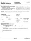
4 1. Remove the motor carefully from its shipping container. 2. Inspect the motor for any damage. 3. Examine the motor frame, front output shaft, and mounting pilot for any defects. 4. Notify the carrier of shipping damage immediately. Remove the Shaft CapRemove the protective cap installed on the motor shaft with your hand or by prying it off with a screwdriver. Do not use a hammer or other tools as they can damage the motor : Do not attempt to open and modify the motor beyond changing the connector orientation as described on page 5. Only a qualified Rockwell Automation employee can service this motor. VP L - x xxx x x - x x 1 x A xFactory OptionsA = StandardS = Shaft sealMounting FlangeA = IEC metric, free mounting holes (type FF)Brake2 = No Brake4 = 24V DC BrakeShaft KeyJ = Shaft keyK = Smooth shaftConnector1 = Single SpeedTec DIN connector, right angle, 325 rotatableFeedbackC = 18-bit absolute single-turn digital encoder (Hiperface DSL protocol)P = 18-bit absolute multi-turn (4096 revolutions) digital encoder (Hiperface DSL protocol)Q = 23-bit absolute multi-turn digital encoder (Hiperface DSL protocol) SIL2/PLd rated, 12-bit secondary safety channel (1)W = 18-bit absolute multi-turn digital encoder (Hiperface DSL protocol) SIL2/PLd rated, 9-bit secondary safety channel (2)Rated Speed (3)A = 1500 rpmD = 3000 rpmM= 6000 rpmB = 2000 rpmE = 3500 rpmT = 6750 rpmC = 2500 rpmF = 4500 rpmU = 8000 rpmMagnet Stack Length (1, 2, 3, 4, 6 stacks) (4)Frame Size - Bolt Circle Diameter (BCD)
5 063 = 63 mm115 = 115 mm075 = 75 mm130 = 130 mm100 = 100 mm165 = 165 mmVoltage ClassA = 200V B = 400V Series TypeL = Low InertiaSeriesVP = Permanent magnet rotary Servo Motors optimized to the ratings of Kinetix 5500 and Kinetix 5700 Servo Automation Publication VPL-IN001E-EN-P - August 20163 Kinetix VP Low Inertia Servo Motors with mm Frame SizeProlong Motor Life Proper design and maintenance can increase the life of a Servo motor. Follow these guidelines to maximize the life of a Servo motor operated within the Environmental Specifications on page 22: Create a drip loop in the single motor cable to carry liquids away from the connection to the motor. Whenever possible, provide shields that protect the motor housing, shaft, seals, and their junctions from contamination by foreign matter or fluids. Shaft seals are subject to wear and require periodic inspection and replacement. Replacement is recommended every 3 months, not to exceed 12 months, depending on use.
6 See Shaft Seal Kits on page 22 for more information. Inspect the motor and seals for damage or wear on a regular basis. If you detect damage or excessive wear, replace the item. Shaft SealsAn additional seal is required on the motor shaft near the motor front bearing if the shaft is exposed to significant amounts of fine dust or fluids, such as lubricating oil from a gearbox. An IP66 rating for the motor requires a shaft seal and environmentally sealed connectors and cables. The additional seal is not recommended in applications where the motor shaft area is free of liquids or fine dust, and a lower rating is sufficient: SeeEnvironmental Specifications on page 22 for a brief description of the IP rating for these Motors . See Shaft Seal Kits on page 22 for seal kits compatible with your motor. See Kinetix Rotary Motion Specifications Technical Data, publication KNX-TD001, for Bulletin 2090 cables with environmentally sealed connectors compatible with these Motors .
7 Couplings and PulleysMechanical connections to the motor shaft, such as couplings and pulleys, require a torsionally rigid coupling or a reinforced timing belt. The high dynamic performance of Servo Motors can cause couplings, pulleys, or belts to loosen or slip over time. A loose or slipping connection causes system instability and can damage the motor shaft. All connections between the system and the Servo motor shaft must be rigid to achieve acceptable response from the system. Periodically inspect connections to verify their rigidity. When mounting couplings or pulleys to the motor shaft, verify that the connections are properly aligned and that axial and radial loads are within the specifications of the motor. SeeLoad Force Ratings on page 11 for guidelines to achieve 20,000 hours of motor bearing life. Prevent Electrical NoiseElectromagnetic interference (EMI), commonly called electrical noise, can affect motor performance. Follow these guidelines to reduce the effects of EMI: Isolate the power transformers or install line filters on all AC input power lines.
8 Use shielded cables. Shield signal cables from power wiring. Do not route motor cables over the vent openings on Servo drives. Ground all equipment by using a single-point parallel ground system that employs ground bus-bars or large straps. If necessary, use additional electrical-noise reduction techniques to reduce EMI in noisy environments. See System Design for Control of Electrical Noise Reference Manual, publication GMC-RM001, for additional information on reducing EMI. Install CablesKnowledgeable cable routing and careful cable construction improves system electromagnetic compatibility (EMC). ATTENTION: Damage can occur to the motor bearings and the feedback device if sharp impact is applied to the shaft during Installation of couplings and pulleys. Damage to the feedback device can result from applying leverage to the motor mounting face when removing devices mounted on the motor shaft. Do not strike the shaft, couplings, or pulleys with tools during Installation or removal.
9 Use a wheel puller, to apply pressure from the user end of the shaft, when attempting to remove any device from the motor shaft. ATTENTION: The overall shield on the single motor cable must be grounded to obtain an effective encoder signal. The encoder data signal is transmitted through an impedance-matched twisted-wire pair that requires effective shielding for optimum performance. Be sure there is an effective connection between the cable shield and the drive system ground. 4 Rockwell Automation Publication VPL-IN001E-EN-P - August 2016 Kinetix VP Low Inertia Servo Motors with mm Frame SizeTo install the single motor cable, observe these guidelines: Keep the cable length as short as possible. Ground the cable shield to prevent EMI from affecting other equipment. Functional SafetyMotors that are equipped with a Hiperface DSL functional safety-rated feedback sensor are designed in compliance with the requirements of the following SICK STEGMANN GmbH documentation to maintain the functional safety rating of the feedback sensor attached.
10 See Catalog Number Explanation on page 2 for details about each T V Rheinland group has approved Kinetix VP low- Inertia Servo Motors equipped with functional-safety certified Hiperface DSL digital encoders to be capable of letting a system achieve a functional safety rating up to Performance Level d (PLd) and safety category 3 (CAT. 3) per EN ISO 13849, and SIL 2 per IEC 61508, EN 61800-5-2, and EN 62061 when used in conjunction with variable frequency drives that satisfy functional safety requirements of the HIPERFACE DSL Safety Manual (SICK STEGMANN GmbH, publication 8017596/YLR0).To view the T V Rheinland certificate and other product certifications currently available from Rockwell Automation, go Safety ConsiderationsIn addition to the Instructions throughout this document, you are also responsible for the following: Complete a machine-level risk assessment. Certification of the machine to the desired EN ISO 13849 performance level or EN 62061 SIL level.