Transcription of KT 76/78 TRANSPONDER INSTAllATION MANUAL 006-0067-01
1 KT 76/78 TRANSPONDER INSTAllATION MANUAL 006-0067-01 R E\1. 1 D E CEMBER, 1972 This equipment manufactured under the following Patent: 3, 366,834 ONE FULL YEAR WARRANTY General Aviation Avionic products manufactured by King Radio Corporation (hereinafter called King) are warranted against defects in design, workmanship and material under normal use for which intended for one year after warranty registration provided such registration occurs within eighteen months of the factory shipping date. King's limit of liability hereunder shall be to provide necessary parts and labor to repair said product, transportation charges prepaid at either King factory or an authorized King Service Center. King shall not be liable for consequential or other damage or expense whatsoever therefore or by reason thereof. This warranty shall not apply to any product which has not been installed by an authorized King INSTAllATION Facility in accordance with the INSTAllATION MANUAL , or which has been repaired or altered in any way so as to adversely effect Its performance or reliability, or which has been subject to misuse, contamination, negligence or accident.
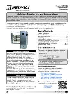
2 This warranty Is in lieu of all other General Aviation Avionics guarantees or warranties expressed or implied. King reserves the right to make design changes. additions to and Improvements in its products without obligation to install such in products previously manufactured. 0 0 0 D 0 D D 0 0 0 0 0 D D 0 0 0 D 411iedSignal AEROSPACE BENDIX/KING Service Aid AlliedSignal General Avia tion Avionics 400 Norrh Rogers Road Ola rhe, Kansas 66062-1212 Service. Aid: KT 76/KT 78-102 TRANSPONDER SUBJECT: Mode A and C updates to improve reliability. Reliability of the KT 76/78 can be improved by removing and replacing the components listed below and careful alignment of the decoder one-shots. Remove and replace the components in the unit with the ones in the following list. COMPONENT PART NUMBER DESCRIPTION 1413 120-00061-0000 IC, SN74221N C426 105-00031-0014 CAP, MY , BOV C429 104-00001-0038 CAP, S/M 2400pf, 1% C430 104-00001-0038 CAP, S/M 2400pf, 1% R474 131-00153-0023 RES, F/C 15 Kolj4W 5% R491 135-00123-0012 RES, M/F 12Ko1/4W 5% R494 133-00113-0015 RES, VAR 2Ko 1W R495 135-00123-0012 RES, M/F 12Ko1j4W 5% Using the procedure in the KT 76/78 Maintenance Overhaul MANUAL align the mode A one-shots at TP403 and TP404 for pS + pS.
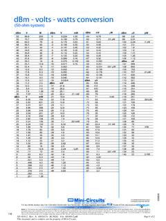
3 Align the mode C one-shots at TP405 and TP406 for pS + ps~ These adjustments should be smooth, if they are erratic, clean or replace the variable resistors as necessary. Date: Oct/93 P/N 601-01340-0020 SA KT 76/ KT 78-102 Page 1 of 1 THIS INFORMATION PROVIDED BY STICKS AND STONES PROD. WE HOPE THAT IT IS USEFUL. J(T 76A Troubt~hootin2 Tips Poor sen$itivity ? When working on a KT 76A that has poor sensitivity, check the following caps: C440, C441, C442, C443, C444. If these caps are black in color, replace them all. The new ~ps will be ):ellow in color. Erratic sensitivity? . When repairing a KT 76 Ayou discover that the unit exhibits erratic sensitivity, check the power supply line. This line should read between and line mea:;ures out of tol~rance, check C409 as this one has been the culprit many times. Rack 'em up The following is a list of mounting rack part . numbers for various panel mount equipment: l;JNIT KJ\.
4 -1A 20 KMA 24 KMA 24H KMA 24H-70171 KN 53 KN 62A lC~ 63 Kl'l 64 KN 74 KT. 76A KT 79 KNS 80 KNS 81 KR 85 KR 86 KR- 87 88 KY 92 KY 96A KY 97A KX 125 KA 134 145 KX; 155 KX 165 KX 170/175/A/B KC 190/1/2 KY l96/l97 KY 196Nl97A RACK PART# 047-01761-0001 047-04940-0004 04 7-04940-0004 047-0475 1-0004 047-04751-0004 047-04543-0002 04 7-04219-0000 047-04543-0002 047-02191-0000 047-Q3898-0002 047-05827-0004 047-05547-0001 047-04899-0001 047-0 l 846-0000 04 7-025 I 0-0001 047-05193-0002 071-01486-0000 071-01541-0000 047-04575-0002 047-08512-0004 04 7-08512-0004 047-06865-0001 047-04567-0002 047-03204-0002 i 047-04874-0001 047-01695-0000 047-05114-0003 047-04676-0004 047-08512-0004 0 0 0 0 0 0 0 0 0 0 0 0 0 0 0 0 0 0 0 0 0 D 0 0 D 0 0 D 0 0 D 0 0 0 0 0 ~ KING KT 76/78 TRANSPONDER TABLE OF CONTENTS SECTION I GENERAL INFORMATION Paragraph 1. 1 Introduction 1. 2 General Description 1. 3 Technical Characteristics 1.
5 4 Units and Accessories Supplied 1. 5 Accessories Not Supplied 1. 6 Lie ense Requirements SECTION II INSTAllATION 2, 1 2. 5 2. 6 3. 1 i 2-1 2-2 2-3 2-4 2-5 2-6 2-7A 2-7B 2 - 8 2-9 3-1 General Unpacking and Inspecting Equipment INSTAllATION Procedures Voltage Changeover Instruction~; KT 76/78 INSTAllATION Connector A ssembly Procedure KA 48 INSTAllATION Location Consideration SECTION Ill OPERATION Normal Operation LIST OF ILLUSTRATIONS KT 76/78 Voltage Changeover of Front Panel Crimping Tool KT 76/78 Interconnect KT 76/78 KA 48 Mounting Acceptable Cable Connections 030-0061 Connector Assembly 030-0101 Connector Assembly Type 11N11 and "C11 Connector Assembly 030-0005 Connector Assembly KT 76/78 TRANSPONDER Controls i Page 1-1 1-1 1-1 1-3 1-4 1-5 2-1 2 - 1 2-1 2-1 2-2 2-3 2-4 2-4 2-1 i 2-2 2-5 2-6 2-7 2-9 2-10 2-11 2-12 2-13 2-13 3-2 ~ KING HISTORY OF REVISIONS REV. 1, December, 1972 Front l-3, 1-4 2-4 2-5 2-6 2-7 2-9 2-10 2-11 2-12 2-13 3-2 Description of C:hange No's Added INSTAllATION Kit Parts Lists Updated Misspelled Word Clarification of "596" Drawing Number Clarification of "696" Drawing Number Revised INSTAllATION Drawing Clarification of 1169611 Drawing Number New Connector Number Shown Clarification 11696" Drawing "Number New Connector Assembly :Procedures Clarification of 11696" Drawing Number Clarification o1 11tl96" Drawing ii 0 0 0 0 0 0 0 0 0 0 0 0 0 0 0 0 0 0 D 0 0 0 0 D 0 0 0 0 0 D 0 0 0 0 0 INTRODUCTION ~ KING KT 76/78 TRANSPONDE R SECTION I GENERAL INFORMATION Thi s MANUAL contains information relative to the physical, mechanica l , and electrical characteristics of the King Corporation Silver Crown KT 76/78 .
6 Information relative to the maintenance, alignment and procurement of replacement parts may be found in KT 76/78 Maintenance/Overhaul MANUAL , KPN 006-5058-00. GENERAL DESCRIPTION The King KT 76 and KT 78 Transponders are radar beacon equipment designed to fulfill the role of the airborne beacon under the requirements of the Traffic Control Radar Beacon System ( ). The KT 76/78 Transponders are capable of locating the user through the air traffic controller. Range and azimuth are established by the return from the TRANSPONDER 's pulsed transmitter in reply to n. routine interrogation from the ground radar site. The TRANSPONDER reply is a set of pulses, selected in number, and positioned in time, one with respect to the other (not entirely unlike telegraphy). Information is conveyed to the ground in this manner. An identity code number, selected at the front panel by the pilot is as a Mode A reply.
7 Mode C, altitude reporting, is an additional capability designed into the TRANSPONDER . However, in order to convey altitude information, the TRANSPONDER must be lised in conjunction with a reporting altimeter and operated in "ALT" function. An additional feature of the TRANSPONDER and beacon system is the S. P. I. (Special Pulse, Identification). After pressing the ident button the TRANSPONDER , when interrogated, will reply with a special pulse that will cause the associate d pip on the controllers display to "bloom" effecting immediate recognition. TECHNICAL CHARACTERISTICS SPECIFICATIONS CHARACTERISTICS TSO COMPLIANCE: C74b TSO CATEGORY: KT 76 -DAPBBBXXXXXX Class 1 KT 78 -DAPBBBXXXXXX Class II Page 1-1 SPECIFICATIONS APPLICABLE DOCUMENTS: TEMPERATURE RANGE: HUMIDITY RANGE: WEIGHT: INSTAllATION SPACE: POWER REQUIREMENTS: ALTITUDE: TRANSMITTEH FREQUENCY: TRANSMITTER POWER: HECEIVER FREQUENCY: RECEIVER SENSITIVITY: MODE A CAPABiliTY: MODE C CAPABIUTY: SIDE LOBE SUPPRESSION: Page 1-2 ~ KING KT 76/78 TRANSPONDER CHARACTEIUSTICS TSO C74b, UTCA D0-138 - 15 C to +55 C for continuous operation Up to 95o/o at +50 C ( +122 F) for 12 hours 3.
8 0 lbs. including Mtg rack 14 volt -6. 25 X 1. 63 X in. ( 15. 88 X 4. ~4 X 25. 4cm) 28 volt-6. 25 X 1. 63 X 11. 00 in. ( 15. 88 X 4. 14 X 27. 94cm) 14 volt 28 volt 1. 3 Amp 1. 3 Amp KT 76 Tested up to 30,000 feet which exceeds TSO requirements. KT 78 up to 15, 000 feet 1090 MHz 3 MHz KT 76 -200 watts peak minimum KT 78 -113 watts peak minimum 1030M:Hz -74dbm nominal -72dbm minimum for 90% reply 4096 identity codes plus SPI pulse. Accepts AIUNC attitude digitizer output, reporting in 100 foot increments from -1000 ft. up to 31,000 feet. 3 pulse 0 D 0 0 0 0 0 0 0 0 [\ 0 0 0 0 0 0 0 0 0 0 0 0 0 D 0 0 0 0 0 0 0 0 0 0 0 .. KING KR 76/78 TRANSPONDER UNITS AND ACCESSORIES SUPPLIED KPN 030-0005-00 030-0101- 00 1,<030-1046-12 030-1050-00 071-1048-00 089-8094-30 090-0019-07 089-2013-37 089-5907-06 089-8027-30 1 o91-oo31-os 089-8110-34 089-5903-04 KPN 04 7-2445-00 089-2016-37 089-5991-12 089-8112-34 132-0113-04 089-2009-37 091-0009-00 089-5878-04 A.]
9 King K'T 76 TRANSPONDER KPN 066-1034-00, 14 VDC King KT 76 TRANSPONDER KPN 066-1034-01, 28 VDC King KT 78 TRANSPONDER KPN 066-1034-02, 14 VDC King KT 78 TRANSPONDER KPN 066-1034-03, 28 VDC Mounting Tray KPN 047-2439-01 (supplied with each unit) B. King KT 76/78 INSTAllATION Kits 1) KPN 050-1244-00 (14 VDC) Parts List as Follows: DESCHIPTION Connector Coax, Tf:o~D #4-10-4 Connector Coax, T:ED /19-30-4 Gold Contact Connector, MOL EX 1917G (This is 12 contacts on a strip) Connector, Housing Antenna KA 48 Washer Flat Retaining Ring Nut, Hex, /16-32 Screw, P. H. PH., #6-32 X 3/8 Washer, Flat, #6 Cable Clamp Lockwasher 1/6 Screw, PHP #4 -40 X 1 /4 QUANTITY 1 1 1 1 1 2 1 1 1 1 1 1 2 2) KPN 050-1244-01 (28 VDC) Parts list as follows: -NOTE-This kit is same as 14 VDC Kit with the addition of the following parts. ION Shield Head Nut Hex 10-32 Screw PHP 10-32 X 3/4 Washer Lock #10 Resistor W/ W 1011, 55W, 5% Nut, Hex, #4-40 Grommet, 1 I 8'' l D.
10 Screw, PHP, #4-40 X 1/4 Springtite QUANTITY 1 2 2 2 1 2 2 2 Hev. 1, December, 1972 Page 1-3 ACCESSORIES NOT SUfj~-LIED .. KING KT 76/78 T HANS PONDER A. Voltage change over kit H'4 to 2 SVOC) 050'-1247-00 Parts List as KPN 047-2445-00 057-1395-01 089-2009-37 089-2016-37 089-5878-04 089-5991-12 089-8112-34 091-0009-00 132-0 113 -04 follows: DESCRIPTION Shield, Heat Voltage Plate &ll v Nut, Rex, #4-40 Nut, Hex, # 10-32 Screw, P. H. P, #4-40 x 1/4 Springtite Screw, PHP 10-32 x 3/ 4 Washer, Lock# 10 , 1/8 I. D. , W. W. 10 ohm, 55W, 5o/o QUANTITY 1 1 2 2 2 2 2 2 1 B. Voltage change over kit (28 to 14 VDC) 050-1247;..01 Parts List as follows: KPN 026-0001-00 057-1395-00 DESCIUPTION QUANTITY Buss \Vire (#26 AWG) 1 ft. Lamp Voltage Plate 14V 1 0 0 0 0 0 0 0 0 0 0 c. Low Loss Antenna INSTAllATION Kit, 050-1253-00 o Parts as follows: KPN 024-0013-00 oao.:.oo92-0tl 030-0102-00 Page 1-4 DESCRIPTION Cable, Coax Connector, Coax 'fED 9-10-5 Connector.