Transcription of L30050EN Grease Jockey Installation and …
1 Grease Jockey Installation and Operation GuideGrease Jockey Installation and Operation GuideL30050 Table of ContentSubject PageSystem Description 1 Component Description Timer 2 Solenoid 2 Air Pumps 3 Modules 3 Meters and Tubing 4 Grease and Kits 4 Electric Pumps 5 Typical System Layout 6 Typical Bill of Materials 7 Installation Steps 1 - Pump Mounting 8 2 - Solenoid 8 3- Timer and Wiring 9 4 - Modules 9-11 5- Tubing 11 6- System Fill/Start 12 7 - Air Purge Lines 12 8 - Warranty Registration 13PM Procedure 15 Troubleshooting 16-17 Parts List 18-20 Grease Jockey Installation and Operation GuideL30050 Page 1 Grease Jockey sysTeM DesCrIPTIONThe Grease Jockey system is controlled by a timer, which activates either an air solenoid valve or an electric motor to drive a pump.
2 The pump supplies Grease into the main supply line for delivery to localized distribution modules are made up of manifolds with metering valves and distribution lines for each lube point in that localized area. The meters are designed to dispense a precise amount of Grease at each lube cycle. Meter size is chosen by a ratio of the smallest to largest lube point requirements in the pump must pressurize the system, then vent it to allow the metering valves to reset for the next cycle. A fluid Grease is required to achieve proper flow and lubrication Jockey Installation and Operation GuideL30050 Page 2sysTeM COMPONeNTsTIMerThe timer (Ref. Fig. 1) on an air operated pump system is a compact solid state device housed in a high impact resistant plastic enclosure.
3 It has seven lube cycle interval settings from 1/2 to 6 hours, plus a test position and a manual run timer operates the system only while the vehicle's ignition is turned on. A memory function keeps track of elapsed-cycle-time even if the ignition switch is turned off. When the predetermined cycle time has elapsed, the timer signals the pump to initiate a lubrication cycle. If the vehicle's ignition is turned off before the interval is complete, the timer's memory "holds" the time count until the vehicle is the cycle-time dial is switched from one range to another, the manual run button should be pressed to initiate the new cycle time setting (otherwise, the new time is added to any time that remains from the previous lube cycle).
4 When rapid repetitive cycles are needed, turn ignition key to "ON", set the cycle-time dial to the "test" position, and press the manual run button. In this mode the timer signals the pump to cycle approximately once every minute. (45 seconds on and 15 seconds off). This rapid cycling continues as long as the timer remains in the "test" position. Always reset the timer dial to it's proper air valve (Ref. Fig. 3) used with the air operated pump threads into the port on the bottom of the pump. It is a 3-way, normally closed, free venting valve available with either a 12 or 24 VDC 9 watt continuous duty rated coil. The coil is molded and potted with a 6" lead of 16 AWG wire and a weather tight (male) connector.
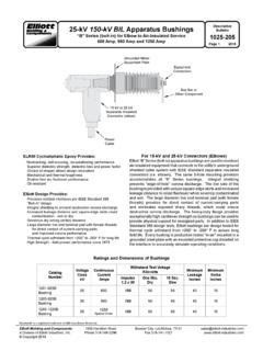
5 The air valve has a 1/8" NPT inlet port and a 1/4" NPT male thread outlet port. The maximum operating pressure is 150 psi. The barbed connector is the exhaust port and should not be blocked. There is a manual test button located on the end above the electrical lead. A 22' wire harness with a weather tight (female) connector to mate with the solenoid is available (included with kits).Figure 1 Figure 3 FIGure 2 reCOMMeNDeD TIMer seTTINGT imer settingDriving or 1 hourOff or 2 hoursStart + stop city, heavy salt, snow and ice, rough pavement, wet climate, heavy loads, dusty roads3 hoursNormal city or highway driving, normal climate, moderate loadsThese are recommended settings only.
6 Experience with individual applications will determine timer Jockey Installation and Operation GuideL30050 Page 3aIr OPeraTeD PuMPThe air pump is designed to dispense a maximum of cubic inches of Grease . The air pressure to the pump must be a minimum of 100 psi and a maximum of 150 psi for the meters to function correctly. The pump is a 9 to 1 ratio pump to provide a Grease pressure output of between 900 and 1350 air pump (Ref. Fig. 4) operates when the 3-way air solenoid valve is actuated by the timer and air pressure is applied to the air chamber port (1) and diaphragm (2). This forces the spring-loaded pump piston (3) upward compressing the Grease in chamber (4).
7 This pressure seats the flapper valve (5) against the reservoir opening (6) and Grease flows toward port (9).Simultaneously, pressure is applied behind the spring-loaded check valve poppet (8) through port (9) sealing off passage way (7). Grease flows into the main lines through outlet (11).After completion of an on-time cycle, the 3-way air valve exhausts the air in the pump. The pump piston spring forces the pump piston (3) down allowing the flapper valve (5) to unseat from the reservoir opening (6). Grease from the reservoir is drawn into chamber (4) just vacated by the pump piston (3). System pressure is relieved through port (9) to port (7) back to the reservoir as check valve (8) is returned by spring (10).
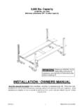
8 MODuLesA module is (Ref. Fig. 5) an assembly that distributes the Grease from the main line to a group of lube points. It is made up of a manifold, mounting stem, meters (metering valves), 3/16" OD tubing, and fittings. One manifold can hold as many as 12 meters. Plugs are available to close off any manifold port that is not required. The manifold mounts with the ported stud through a 5/8" hole. Main lines may be connected at either end of the manifold or at the end of the mounting (15 to 22 ft/lb. Torque)Figure 4 Figure 5 Grease Jockey Installation and Operation GuideL30050 Page 4 MeTersMeters (Ref. Fig. 6) are positive displacement, spring-reloaded, dispensing devices designed for use in Grease Jockey systems operating at 900 to 1200 psi.
9 These meters are available in 6 sizes (based on output volume) to meet various lube requirements. These 6 sizes provide adequate choices to supply every lube point on a truck chassis, including the fifth wheel. (See Fig. 7)Request document GJ-00003 for additional meter information. Request document GJ-00006 for instruction on changing meter Grease Jockey heavy wall nylon tubing should be used in the system. Use 3/16" OD lines for lube point distribution and 5/16" OD for main lines with brass fittings. (Tube inserts are required on ALL 5/16" line connections). Other adapters, fittings, connectors, and mounting hardware are available from your Grease Jockey distributor.
10 CauTION: DO NOT substitute air brake tubing for lube lines. The pressure rating is NOT adequate for Grease Jockey lubrication system fluid lithium Grease of NLGI grade "0" or "00" with an "EP" additive is standard for this type system. A 35lb pail of "00" Grease , 550-400-020, is available from your Grease Jockey distributor. Grease should not contain suspended lubricating agents such as graphite or moly disulfide. Request document GJ-00003 for additional Grease information. high OuTPuT MeTer BODyOuTPuT eNDMeTer VaLVe asseMBLy5/8 HeXOuTPuT sPaCer WasHer5/8 HeX"O" rINGMeTer BODy"O" rINGF igure 6 FIGure 7 MeTer CHaraCTerIsTICssizeNo. Washers in Meter BodyTurned Jockey Installation and Operation GuideL30050 Page 5eLeCTrIC MOTOr DrIVeN PuMPThe motor (1) is energized.