Transcription of Lab 3: Low Pass and High Pass Filters
1 Page 1 of 7 Rev CLab 3: Low Pass and High Pass FiltersPurposeThe purpose of this lab is to introduce you to Low Pass and High Pass Filters . As part ofperforming this lab you will Determine the amplitude and frequency response characteristics of Low and HighPass Filters , Compare passive and active LPF and HPF filter configurations, and Compare theoretical models with actual this experiment you will design, build1, and test four Filters . The configurations you will buildare Passive Low-Pass Filter, Active Low-Pass Filter, Passive High-Pass Filter, and Active High-Pass each of the configurations you will1. Design the filter for a specified cut-off frequency,2. Model the filter in MatLab,3. Simulate the design with PSpice2, and4. Test the design in the 1, 2, and 3 are Prelab activities. Step 4 will be performed during the lab your report you will compare the theoretical and actual amplitude and phase plots for each ofthe four you are rusty on transfer functions or op amp usage you may want to review those subjects.
2 1 UTD will supply integrated circuits, the student is expected to purchase resistors and capacitors. SeeIntroduction to Communications System Labs, page PSpice is available on the Communications Lab PCs. A free demo version may be obtained from MicroSim bycalling (800) 245-3022. A limited number of copies are available for check out from Steve Gibbs, EC 2 of 7 Rev CPrelab 3. LPF and HPFP relab Introduction to Draw graphs showing the frequency responses of an ideal low-pass filter (LPF) and anideal high-pass (HPF) Generate a signal in MatLab composed of two sine waves using the followingparameters:a) f1 = 2000 Hzb) f2 = 40000 Hzc) 0 t 2 millisecondsd) Ts = 5 microsecondse) y(t) = sin ( 2 f1 t ) + cos ( 2 f2 t )3. Plot the time domain and the frequency domain representations of the "Filter" the wave form by "zeroing out" the high frequency components of the FFT waveform: There are two ways in MatLab to "filter" a wave form.
3 One technique is to "zero out" thehigher frequency elements of the FFT. The other is to use the transfer function of a lowpass filter. In the steps below you will zero out the high frequency elements of the ) % create a new vector containing only the lowb) % frequency components of Yc) L = length(Y);d) NewY = zeros(L,1);e) % define the number of data points to copy from the original filef) NewY(1:b)=Y(1:b); As an option, instead of replacing the values of higher frequency region with zeros, it is alsofeasible to replace the original values with very small values, such as , whichrepresent out of band noise. Although at this point you are not actually filtering the signal, you are performing the same kindof function that a Low Pass Filter performs. The performance of this filtering methoddepends on the number of vector elements you replace with zeros in the high frequencycomponents of the After filtering in the frequency domain, reconstruct the signal using "ifft".
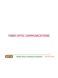
4 In your report, compare the reconstructed signal with the original signal in the time Repeat this procedure for the lower frequency region of the FFT and observe the output. This method introduces the concept of filtering. This filtering is considered ideal filtering interms of the performance of the filtering. However this filtering requires additionalprocedure for reconstruction of the signal. In the real world the goal is to design filtersthat perform as well as this 3 of 7 Rev C7. Use Convolution to demonstrate filtering. (This will use the convolution technique youused in Lab 2.)a) Determine the impulse response of the ) Convolve the impulse response of the filter with the signal that you are going simulates LPF filtering using this filtering method in MatLab. In your LabReport, comment on the performance of the MicroSim Simulation1. Build the following passive low-pass filter in MicroSim and determine its transfer functionand cut-off frequency: 2.
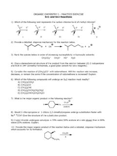
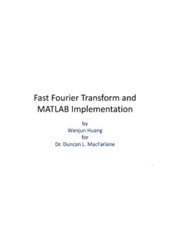
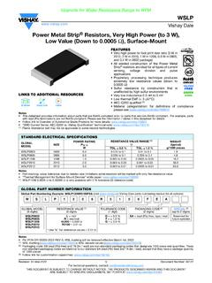
5 Build the following passive high-pass filter in MicroSim and determine its transfer functionand cut-off frequency: Figure 2. RC High Pass FilterPage 4 of 7 Rev C3. Build the following active low-pass filter in MicroSim and determine its transfer function andcut-off frequency: 4. Build the following active high-pass filter in MicroSim and determine its transfer functionand cut-off frequency:Figure 3. Sallen-Key Equal Component Active Low Pass FilterFigure 4. Sallen-Key Equal Component Active High Pass FilterPage 5 of 7 Rev CLab Period Low Pass and High Pass FiltersParts required for this lab:Resistors:Determined by circuitCapacitors:Determined by circuitIntegrated circuits:2 Op-amp uA741 Lab Frequency response of a RC low pass filter In this section you will determine the frequency response of an RC Low Pass Filter. Also, youwill verify the filtering process by applying the sum of two sinusoids at the input andmeasuring the attenuation caused by the filter on the amplitudes of the two signals.
6 Hint: If you decide to print the graphs from LabVIEW during the lab period, you may want tozoom the display to improve the resolution of the plots before you print Build the circuit shown in Figure 1. Manually determine its cut-off frequency. Recall thatvoltage at the cut-off frequency is (- 3 dB) times the input voltage to the channel 2 of the oscilloscope to the input and channel 1 to the Use to obtain the frequency response of this filter. Enter the parameters forthe sweep. Use Lowfreq = 100 Hz, Upperfreq = 100000 Hz, Amplitude = 10 V,points/decade = 10. Note the GPIB address of the signal generator that you are an appropriate filename to save the data in the "Data file" box. Remember to use adifferent filename each time that you run the Notice that the frequency axis in the graph has a logarithmic scale. Report the cut-offfrequency by finding the -3 dB point ( the point which is 3 dB below the maximumamplitude).
7 Also, find the amplitudes at f1 = 10 kHz and f2 = 100 kHz. Cut-off frequency (fc) = Amplitude at f1 (m1) = Amplitude at f2 (m2) = 4. From the last two coordinates, estimate the slope of the magnitude response. Determine thephase shift at the cut-off frequency. Derive a function to determine the phase shift of thiscircuit and calculate the phase shift at the theoretical cut-off frequency. Compare it with themeasured value. Slope (dB/decade) = Phase shift at cut-off frequency = Theoretical = Measured = Page 6 of 7 Rev C Hint: To make the measurements easier, zoom in on the graph by changing the lower and uppervalues shown for each axis. Select by clicking on the parameter to be changed and enter thenew Disconnect the signal generator from the circuit.
8 Connect the ground clips of the two signalgenerators to the circuit ground, and the red test leads to the circuit's input. Set both signalgenerators to produce 10 VPP sine waves. Set one of the function generators to produce a10 kHz sine wave, and the other function generator to 100 kHz. Connect channel 1 of theoscilloscope to the same point as the red clips. Connect oscilloscope channel 2 to Using , obtain the frequency spectrum of the input signal. Enter ts = 8E-3 asthe time span in the control panel of the VI. Measure the amplitude of the main peaks of thespectrum. Amplitude at f1 (pi1) = Amplitude at f2 (pi2) = 3. Apply the signal to the circuit by connecting the leads as shown in Figure 5. Move thechannel 1 probe to the output of the RC Low Pass Filter. Run using thesame time span, remember to save the data with a different filename.
9 Measure the amplitudeof the main peaks in the displayed spectrum. Amplitude at f1 (po1) = Amplitude at f2 (po2) = 4. What is the relationship between m1, pi1 and po1? Verify your conclusion with m2, pi2 Frequency response of an RC High Pass Filter1. Construct an RC High Pass Filter as shown in Figure Repeat the procedure described in LAB to analyze the frequency response of the RCHigh Pass Filter. Use f1=100 Hz, f2 =1000 Hz, and ts = ( 500E-3).Function Generator 1 Function Generator 2 Red Test LeadRed Test LeadBlack Test LeadBlack Test LeadFigure 5. Function Generator Connection for LPF and HPF FiltersPage 7 of 7 Rev CLab Frequency response of an active low-pass active1. Construct the active Low Pass Filter shown in Figure 3 using the following parameters:. Equipment Settings: VCC18 V (power supply voltages) VSS -18 V f1 3,000 Hz f2 30,000 Hz Amplitude5 Vpp LabVIEW Settings: Lowfreq100 Hz Upperfreq30 kHz points/decade10 ts20E-32.
10 Analyze the response of the filter by following the steps of Lab Frequency response of a high-pass active Construct the active High Pass Filter shown in Figure 4 using the following parameters: Equipment Settings: VCC18 V VSS-18 V f150 Hz f2500 Hz Amplitude5 VPP LabVIEW Settings: Lowfreq50 Hz Upperfreq50 kHz points/decade10 Analyze the response of the filter by following the steps of Lab not disassemble the active Filters , they will be used in the Lab ReportDuring this Lab you modeled and built several different low pass and high pass Filters . In yourreport, Compare the frequency and phase responses of all the Low Pass Filters . Compare the frequency and phase responses of all the High Pass Filters . Explain any discrepancies you noted between the models and the actual circuits. Note any deviations you made from the assigned procedure. The Filters designed in this lab were limited to first or second order Filters .