Transcription of Lab 8 Reflection and Refraction
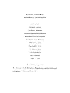
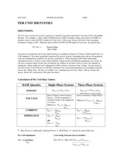
1 1 Reflection and Refraction Goal: To study the Reflection of light by a flat surface and to study the Refraction of light through straight and curved surfaces. Lab Preparation When light travelling through air encounters a different material, part of the light energy is reflected back into the air and part of it is transmitted into the glass, experiencing an abrupt change in direction at the glass surface (Figure 1). This change in direction of the transmitted light is Refraction . Directions of the light rays are specified with respect to a line drawn normal to the glass surface (called the normal line). Figure 1 shows an incident light ray, and the resulting reflected and refracted rays. Figure 1 Here, i is the angle of incidence, r is the angle of Reflection , and t is the angle of Refraction . Note that all angles are measured from the normal line.
2 Law of Reflection . The law of Reflection states the angle of incidence is equal to the angle of Reflection . Thus i = r. Law of Refraction . Snell's law relates the angle of incidence to the angle of Refraction . Snell's law is stated as n1sin 1 = n2sin 2 or n1sin i = n2sin t Here, n1 and n2 refer to the indices of Refraction of the two materials or in other words their optical densities. The index of Refraction in air is nair = In this lab your light will start in air so you will know n1. During the lab you will attempt to measure the angles ( i and t) and use these to determine the index of Refraction of the given material (n2). AirGlassIncidentReflectedRefractedeieret 2 Equipment Lasers. A laser will be used in this lab to trace light rays. Lasers provide high intensity light so they must be handled very carefully in lab.
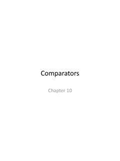
3 Never look directly into the laser light and be very careful that it is not pointing at other people in the lab. Procedure I. The law of Reflection Consider light rays coming from an object, O (see Figure 2). Each ray that falls on a mirror produces a reflected ray. These reflected rays, when extended back into the region behind the mirror, intersect at point I called the image. We wish to locate experimentally the position of the image. Figure 2 A. Using a sharp pencil, draw a line down the center of a sheet of plain paper parallel to its long edge. Set the front edge of the mirror on the pencil line (the front side is the reflecting side of these mirrors). Insert a pin (make sure it is vertical) at O, about 2 or 3 cm from the edge of the page. This will be your object. B. You want to locate the image of O in the mirror.
4 With one eye closed look with the other at the image I in the mirror (Figure 2). Keep your eye at least 1/2 meter away from the mirror. Place two pins at points a (near the edge of the paper) and b (near the mirror) so these points, your eye, and the image of object O are all in the same line (see Figure 2). When the alignment is perfect, the two pins a and b will exactly cover up the image c O I a b d N Mirror your eye 3 of object O since all are in the same line. Remove the pins and label each of these pin holes with the number 1. C. Repeat the process in part B two more times with your eye at different locations. Do this one more time on the same side of the object, as done in part B, and repeat the process on the other side of the object (such as points c and d in Figure 2). Remove the pins each time and label the associated pinholes in the paper with 2's, 3's, and 4's.
5 Make sure at least two of your cases will have angles of incidence of 30o or more. D. Remove the mirror from your paper and draw the following lines for ray set 1 (the pin holes for a and b labeled 1). 1. Draw a solid line through the pin holes a and b to the line that represents the mirror (shown in Figure 2 at point N). 2. Draw a solid line from the object O (you can remove the object and use its pinhole) to point N (shown in Figure 2). 3. You now have a pair of incident and reflected rays like those shown in Figure 1. Using a protractor, construct a normal line to the mirror at point N. Measure the angle of incidence and the angle of Reflection . Record these values in a table similar to the one below. Repeat this process for the remaining three ray sets. Do your measurements support the law of Reflection ?
6 Ray Set i r 1 2 3 4. Extend the four reflected rays back into the region behind the mirror with a dashed line (see Figure 2 again). Ideally, these lines will all intersect at a single point indicating the location of the image I. Because of error in precisely aligning pins and images, all four lines may not intersect at the same place. Draw the smallest circle that includes all points of intersection between the lines. Take the center of this circle as the best average location of the image. Measure and record the distance from mirror to image and from mirror to object. Are these distances the same? Comment on any error. 5. For an alternative method of locating a mirror image carry out the following steps. Place the mirror back on the line and place a pin back in the object location at O.
7 Remove all other pins. Look into the mirror at the image of O. Now, look over the top of the mirror at a second pin held in your hand behind the mirror. You should be able to see this second pin and the image of O in the mirror at the same time. We want to place this second pin at the location of the image I. To do this, move your head from side to side; adjust the second pin so there is no relative motion between this second pin and the image of the pin at O. In other words, when you move your head side to side the second pin 4 and the image of the pin at O should move together back and forth together as you move your head. If one moves more than the other you need to adjust the second pin. When adjustment is perfect, insert the second pin in the board.
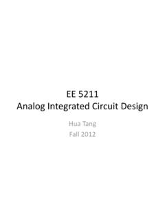
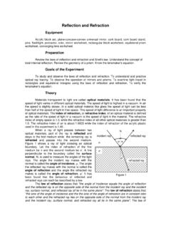
8 Check again by moving your head a lot from side to side. If there is no relative motion between the second pin the image of the pin at O, we say there is no parallax and the second pin and the image of the pin at O are at the same place. Mark this location on your page and label it Image parallax method. II. The law of Refraction - Snell's law *Never look directly into the laser beam or aim it at another person. Please handle carefully. A laser can be used to observe the path taken by light -rays passing through different media. A block of Plexiglas will play the role of the Refraction block shown in Figure 3. A small portion of the laser light is scattered as it passes through the block, making the path evident. Outside the Plexiglas the laser beam can be traced using pins. Figure 3 A.
9 Center the Plexiglas block on a sheet of paper as in Figure 3 and draw a careful outline of the block on the paper. B. Set the laser up so it enters the glass at an angle of incidence of about 50o ( i in the Figure 4). C. Follow the refracted ray as it exits the block into the air on the other side of the block. Use a pin to follow the beam in air and punch small holes in the paper at two widely separated points along the ray exiting the block. Take eietLaserer11n1n2n1 Refraction block1 i' t' 5 care to keep the pin vertical. Put one hole near the block and one further away (dots are shown in Figure 3). D. Repeat this process for the reflected ray (the incident light ray hits the block and some of the light reflects off). Once again put two small holes in the paper, one close to the block and one further away. E.
10 Repeat this process one more time for the incident ray (from the laser to the block). F. Remove the block and use the holes to draw the incident ray, reflected ray, the ray through the block, and the refracted ray. G. Where the incident ray enters the block, construct a normal to the block surface. Measure the angle of incidence, i, and the angle of the refracted transmitted ray in the block, t. Repeat this process where the ray exits the block (construct a normal and measure t and i ). Record these values as trial 1 in tables similar to the ones below. H. For each case ( light entering and light leaving) use the angles and Snell's law to find the index of Refraction of the Plexiglas block. Assume that nair = light Entering light Leaving Trial i t n 1 2 I. Carefully put the block back in the outline and repeat steps B through H with an angle of about 70o.