Transcription of LAB MANUAL for Computer Network
1 LAB MANUALforComputer NetworkDEPARTMENT OF ELECTRONICS & COMMUNICATION ENGINEERINGSRI JAYACHAMARAJENDRA COLLEGE OF of different types of Network cables and Practically implementthecross-wired cable and straight through cable using clamping of Network Devices in of Network the computers in Local Area of basic Network command and Network an Initial Switch Configuration7 Performing an Initial Router Configuration8 Configuring and Troubleshooting a Switched Network9 Connecting a Switch10 Configuring WEP on a Wireless Router11 Using the Cisco IOS Show Commands12 Examining WAN Connections13 Interpreting Ping and Traceroute Output14 Demonstrating Distribution Layer Functions15 Placing ACLs16 Exploring Different LAN Switch Options17 Implementing an IP Addressing Scheme18 Examining Network AddressTranslation (NAT)19 Observing Static and Dynamic Routing20 Configuring Ethernet and Serial Interfaces21 Configuring a Default Route22 Configuring Static and Default Routes23 Configuring RIP24 Planning Network -based Firewalls25 Configuring aCisco Router as a DHCP ServerExperiment-1 Aim:Study of different types of Network cables and Practically implement the cross-wiredcable and straight through cable using clamping (Components).
2 RJ-45 connector, Climping Tool, Twisted pair CableProcedure:To do these practical following steps should be by stripping off about 2 inches of the plastic jacket off the end of the cable. Be verycareful at this point, as to not nick or cutinto the wires, which are inside. Doing so could alterthe characteristics of your cable, or even worse render is useless. Check the wires, one more timefor nicks or cuts. If there are any, just whack the whole end off, and start the wires apart, but be sure to hold onto the base of the jacket with your other do not want the wires to become untwisted down inside the jacket. Category 5 cable mustonly have 1/2 of an inch of 'untwisted' wire at the end; otherwise it will be 'out of spec'.
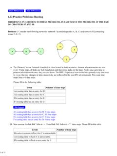
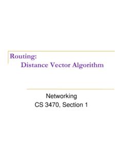
3 At thispoint, you obviously have ALOT more than 1/2 of an inch of un-twisted have 2 end jacks, which must be installed on your cable. If you are using a pre-madecable, with one of the ends whacked off, you only have one end to install-thecrossed over are two diagrams, which show how you need to arrange the cables for each type of cableend. Decide at this point which end you are making and examine the associated picture shows you how to prepare Cross wiredconnectionDiagram shows you how to prepare straight through wired connectionExperiment-2 Aim:Study of following Network Devices in Detail Repeater Hub Switch Bridge Router Gate WayApparatus (Software):Nosoftware or hardware :Following should be done to understand this :Functioning at Physical an electronic device that receives asignal and retransmits it at a higher level and/or higher power, or ontothe other side of anobstruction, so that the signal can cover longer distances.
4 Repeater have two ports ,so cannot beuse to connect for more than two :AnEthernet hub,active hub, Network hub,repeater hub,huborconcentratoris a devicefor connecting multiple twisted pair or fiber optic Ethernet devices together andmaking them act as a single Network segment. Hubs work at the physical layer (layer 1) of theOSI model. The device is a form of multiport repeater. Repeater hubs also participate in collisiondetection, forwarding a jam signal to all ports if it detects a :Anetwork switchorswitching hubis a Computer networking device that connectsnetwork term commonly refers to a Network bridge that processesand routes dataat the data link layer (layer 2) of the OSI model.
5 Switches that additionally process data at thenetwork layer (layer 3 and above) are often referred to as Layer 3 switches or :Anetwork bridgeconnects multiple Network segments at the data link layer (Layer2) of the OSI model. In Ethernet networks, the termbridgeformally means a device that behavesaccording to the IEEE standard. A bridge and switch are very much alike; a switch beinga bridge with numerous 2 switchis often used interchangeably can analyze incoming data packets to determine if the bridge is able to send thegiven packet to another segment of the :Arouteris an electronicdevice that interconnects two or more Computer networks,and selectively interchanges packets of data between them.
6 Each data packet contains addressinformation that a router can use to determine if the source and destination are on the samenetwork, or if the data packet must be transferred from one Network to another. Where multiplerouters are used in a large collection of interconnected networks, the routers exchangeinformation about target system addresses, so that each router can build up a table showing thepreferred paths between any two systems on the interconnected Way:In a communications Network , a Network node equipped for interfacing withanother Network that uses different protocols. A gateway may contain devices such as protocol translators, impedance matchingdevices, rate converters, fault isolators, or signal translators as necessary to providesystem interoperability.
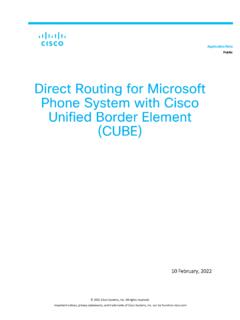
7 It also requires the establishment of mutually acceptableadministrative procedures between both networks. A protocol translation/mapping gateway interconnects networks with different networkprotocol technologies by performing the required protocol :Study of Network IPExperiment-3 Classification of IP address Sub netting Super nettingApparatus (Software):NAProcedure:Following is required to be study under this practical. Classification of IP addressAs show in figure we teach how the ip addresses are classified and when they are used. Sub nettingWhy we Develop sub netting and How to calculate subnet mask and how to identify subnet address.
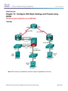
8 Super nettingWhy we develop super netting and How to calculate supernet mask and how to identify RangeSupportsClass 16 million hosts on each of 127 to 65,000 hosts on each of 16,000 to 254 hosts on each of 2 million to for multicast to :Connectthe computers in Local Area : On the host computerOn the host Computer , follow these steps to share the Internet on to the host Computer as Administrator or as , and then clickControl and Internet the connection that youuse to connect to the Internet. For example, if youconnect to the Internet by using a modem, right-click the connection that you want under Dial-up/ other Network Connection Sharing, select theAllow other Network users to connectthrough this Computer 's Internet connectioncheck you are sharing a dial-up Internet connection, select theEstablish a dial-up connectionwhenever a Computer on my Network attempts to access the Internetcheck box if youwant to permit your Computer to automatically connect to the You receive the following message.
9 When Internet Connection Sharing is enabled, your LAN adapter will be set to use IP Your Computer may loseconnectivity with other computers on your Network . Ifthese other computers have static IP addresses, it is a good idea to set them to obtain their IPaddresses automatically. Are you sure you want to enable Internet Connection Sharing? connection to the Internet is shared to other computers on the local area Network (LAN).The Network adapter that is connected to the LAN is configured with a static IP address and a subnet mask of the client computerTo connect to theInternet by using the shared connection, you must confirm the LAN adapter IPconfiguration, and then configure the client Computer .
10 To confirm the LAN adapter IPconfiguration, follow these on to the client Computer as Administrator or as , and then clickControl and Internet Area Connectionand then theGeneraltab, clickInternet protocol (TCP/IP)in theconnection uses the followingitemslist, and then theInternet protocol (TCP/IP) Propertiesdialog box, clickObtain an IP addressautomatically(if it is not already selected), and then :You can also assign a uniquestatic IP address in the range of to254. For example, you can assign the following static IP address, subnet mask, and default Address mask gateway theLocal Area Connection Propertiesdialog box, Control :Study of basic Network command and Network configuration (Software):Command Prompt And Packet :To do this EXPERIMENT-follows these steps.