Transcription of Laboratory Exhaust Systems - Greenheck
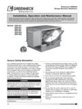
1 Laboratory Exhaust SystemsVektor -HS, Vektor -MS and Vektor -CSwith Variable Geometry NozzleSeptember201722 Vektor -HS, Vektor -MS and Vektor -CSVektor-HS, Vektor-MS and Vektor-CS are Listed for Electrical UL/cUL 705 File no. 40001 Vektor Variable Geometry Nozzle PatentsManufactured by Greenheck Fan Corp. and Foreign Patents PendingGreenheck s Variable Geometry Nozzle Exhaust Systems allow for the safe use of a variable frequency drive to adjust the lab Exhaust fan flow based on actual system demand. As Exhaust airflow adjusts through the high plume Exhaust fans, our integral flow monitoring station and preprogrammed controls adjust the nozzle position to maintain a safe exit velocity per ANSI This is an ideal energy saving solution for Laboratory and fume Exhaust Systems with high variability in peak and downtime demand such as school and university teaching Maintains safe discharge velocity per design or ANSI (3000 or m/s)
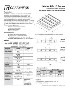
2 Integral flow monitoring with fan venturi Preprogrammed nozzle control to monitor fan airflow and adjust nozzle position Reduces or eliminates need for bypass air which can further reduce system sound levels Assists in overall sound reduction during non-peak conditions such as nights and weekends Typical payback less than two years and may be eligible for local utility rebates Quick single cable connection provides easy installationVektor-HSVektor-MSVektor-CSW heel TypeCentrifugal (Backward Inclined)Mixed Flow (Backward Curved)Centrifugal (Backward Inclined or Airfoil)Peak Airflow & Pressure (per fan)26,000 cfm (44,200 m3/hr) in. wg (870 Pa)32,000 cfm (54,400 m3/hr)10 in.
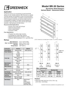
3 Wg (2,490 Pa)32,000 cfm (54,400 m3/hr)10 in. wg (2,490 Pa)Drive TypeBelt driveDirect or belt driveDirect or belt driveHousing ConstructionBelts and drives sealed from contaminated airstreamAMCA Spark BBifurcated housing isolates drive components from contaminated airstreamAMCA Spark B or CDrive components isolated from contaminated airstreamAMCA Spark B or CFans Per Common PlenumUp to 3Up to 4Up to 4 ConstructionAMCA Spark B explosion resistant constructionAMCA Spark B or C explosion resistant constructionAMCA Spark B or C explosion resistant constructionCertifications- AMCA Air Performance- Florida Product Approval & NOA Certification- UL 705 Listed for Electrical- Texas Department of Insurance RV-88- AMCA Sound and Air
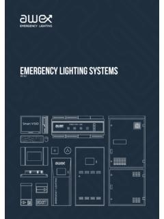
4 Performance- UL 705 Listed for Electrical- AMCA Sound and Air Performance- UL 705 Listed for Electrical- OSHPD-0503-10 Vektor-HSVektor-MSVektor-CSReduceSoundRe duceCostReduceEnergy33 Variable Geometry Nozzle SystemAll Vektor models: Meet ANSI and ASHRAE Laboratory design standards Assemblies are vibration tested to AMCA standard 204-05 Can withstand 125 mph (241 kph) windload without guy wiresFan speed controlled by BMS through VFD supplied by Geometry Nozzle (VGN) with adjustable blades maintain a programmed discharge velocity. Durable blade edge seals Bearings are maintenance free Stainless steel axles1 Modulating actuators with position feedback are housed in weather tight enclosure and easily removable access pressure transducer provides real-time electronic signal of fan non-invasive flow measurement uses pressure differential to provide accuracy within 3%.
5 3 VGN Controller for Single or Multiple FansGreenheck supplied VGN controller adjusts nozzle based on individual fan volume. Preprogrammed logic relates volume to velocity and actuator position Single controller can direct up to four fans NEMA-3R enclosure for indoor or outdoor mounting Feedback to building management system (BMS) for airflow and alarm45123 Velocity by DemandThe VGN Controller accepts input signal from building management system (BMS) for on-the-fly set point velocity adjustments. React to changing conditions such as wind speed, wind direction, or Laboratory sensor readings. Velocity range of 2,000 to 4,000 fpm44 VGN vs Bypass Damper system Performance132 VAV Laboratory Exhaust Fan system OperationLaboratory Exhaust fans have requirements not found in general Exhaust ventilation applications.
6 These safety requirements increase overall energy consumption making Laboratory Exhaust fans notorious energy reduce costs, laboratories commonly utilize variable air volume (VAV) designs, but how the Exhaust fan system is designed and controlled can mean additional energy cost Fan system OptionsSystem with Bypass DamperFan speed and fan Exhaust volume are held constant while the bypass air damper draws outdoor air and modulates to maintain a set static pressure in the ductwork as Laboratory airflow demand with VFD ControlIncorporates a variable frequency drive (VFD) to vary the Exhaust fan motor speed, maintaining static pressure in the ductwork. The Exhaust fan(s) and their discharge outlet nozzle(s) are sized such that the ANSI required 3,000 fpm discharge velocity is maintained at the lowest airflow from the Laboratory .
7 Fan operates at minimum velocity only during minimum lab flow and at higher velocity and horsepower in all other Sequence1. Static pressure sensor to detect system pressure changes*2. building management system (BMS) or controller monitors duct pressure*3. Bypass Damper - Signal to modulating bypass air damper to balance duct system pressure OR3. VFD Control - Signal to VFD adjusts fan volume to balance duct system pressure* Supplied by othersAdvantages: Constant plume heightDisadvantages: Constant fan volume without reduction in fan energy Controls for bypass damperAdvantages: Maintains outlet velocity even at lowest performanceDisadvantages: Over sizes fan motor and electric wiring Higher first cost Higher sound levels Higher velocities and overall power requirements55 Variable Geometry Nozzle (VGN) PerformanceSystem with VGN ControlVGN technology works in conjunction with an Exhaust fan, VFD and building management system to maintain a minimum outlet velocity as Laboratory airflow demand changes.
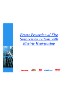
8 When airflow demand changes, the fan speed is adjusted through a VFD to maintain static pressure in the ductwork, and simultaneously the nozzle outlet area modulates by adjusting the two nozzle blades. By modulating the outlet area, a constant discharge velocity can be maintained. Exhaust system operates at varying RPM, volume and : Maintains outlet velocity even at lowest performance Lower sound levels at maximum volume Minimizes horsepowerDisadvantages: Higher first costOperating Sequence1. Static pressure sensor to detect system pressure changes*2. building management system (BMS) or controller monitors duct pressure*3. Signal to VFD adjusting fan volume to balance duct system pressure4.
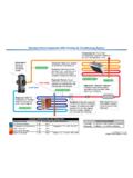
9 Sure-Aire flow measurement signal to VGN controller 5. Nozzle controller 6. Signal to variable geometry nozzle maintaining set discharge velocity 7. Feedback sent back to BMS, including airflow and alarms* Supplied by others Supplied by Greenheck6341275 Performance Comparison ExampleThe following table contains information for fan selections made based on the three operating methods discussed. The selection criteria for these selections are as follows: Maximum airflow: 10,000 cfm External static pressure 1 in. wg Minimum airflow: 5,000 cfm Minimum discharge velocity of 3,000 fpmExhaust SystemFan Size/Nozzle Dia. (in.)Motor HPMinimum Operating PointMaximum Operating PointBrake HPDischarge Velocity (fpm)dBA @ 5 HPDischarge Velocity (fpm)dBA @ 5 Damper24 / , ,18578 VFD Control24 / , ,32980 VGN Control24 / , ,00077 Selections were made using a direct drive, bifurcated inline Laboratory Exhaust fan with mixed flow fans with the Variable Geometry Nozzle have a lower brake horsepower and reduced sound, while maintaining a safe nozzle discharge Installation GuideField WiringGFC Provided CablesIncoming Power Options:120V, 208V, 240V, 480V1PH, 15 Amp Circuit2 VGN Controller Box8 pin cable3 1 Pressure Transducer BoxVFD Connection.
10 24 VAC fan run signal from VFD to 1 FNRUN and +24 VNOTE: Repeat above steps for fan number 2, 3, 4 if Connection:Analog BMS Communications: (all hardwire connections)Nozzle Feedback - connect to 1 NZFB1 and COM, 1 NZB2 and COMFan Flow - connect to 1 SURAR and COMNOTE: Repeat above steps for fan number 2, 3, 4 if applicableAlarm - connect to ALM1 and ALMCOM5 pin cable4 Mount VGN controller box upright with connectors down on structural support within 20 feet from center of fan : Duct pressure modulation, fan speed, isolation damper and bypass damper control wiring is by in Four Steps:1. Connect 5 pin cable from nozzle to factory-mounted pressure transducer box (repeat step for number of fans installed).