Transcription of LABORATORY MANUAL - IIT Kanpur
1 LABORATORY MANUAL MANUFACTURING PROCESSES 1 TA 202 LAB Department of Mechanical Engineering INDIAN INSTITUTE OF TECHNOLOGY Kanpur GENERAL INSTRUCTIONS 1. Every student should obtain a set of instruction sheets entitled manufacturing processes LABORATORY . 2. For reasons of safety, every student must come to the LABORATORY in shoes. It is unsafe for the students to come to the LABORATORY wearing garments with parts that that hang about loosely. Students should preferably use half-sleeve shirts. The Students should also ensure that floor around the machine is clear and dry (not oily) to avoid slipping. 3. An apron will be issued to each student. Students not wearing an apron will not be permitted to the work in the LABORATORY . 4. Instruments and tools will be issued from the tool room. Every student must produce his identity card for the purpose. Tools, etc. must be retuned to the tool room on the same day.
2 5. The student should take the permission of the Lab Staff / Tutor before handling any machine. 6. The student should not lean on the machine when it is working. 7. Power to the machines will be put off 10 minutes before the end of LABORATORY session to allow the students to return the tools. 8. Students are required to clear off the chips from the machine and lubricate the guides etc. at the end of the session. 9. LABORATORY reports should be submitted on A4 size sheets. 10. Reports will not be returned to the students. Students may see the graded reports in the LABORATORY Manufacturing Processes I Page - 1 ME - LABORATORY GENERAL INFORMATION This LABORATORY is aimed at providing an introduction to the Know-how of common processes used in industries for manufacturing parts by removal of material in a controlled manner. Auxiliary methods for machining to desired accuracy and quality will also be covered.
3 The emphasis throughout the LABORATORY course will be on understanding the basic features of the processes rather than details of constructions of machine, or common practices in manufacturing or acquiring skill in the operation of machines. Evidently, acquaintance with the machine is desirable and the LABORATORY sessions will provide adequate opportunity for this. LABORATORY EXERCISE I Turning (T) & NC Demonstration II Milling III Drilling and Fitting (D&F) IV CNC Exercise 6 hr. 3 hr. 3 hr. 3 hr. LABORATORY EXERCISE I Turning (T) & Demonstration & Practice 3hrs. II Milling & Shaping Demonstration & Practice 3 hrs. III Drilling and Fitting (D&F) Demonstration & Practice 3 hrs. IV CNC , Demonstration 3 hrs. V CNC Practice 3 hrs. LABORATORY EXERCISES SCHEDULE.
4 EXERCISE POWER TRANSMITION Video Clip (10 MIN,) LAB TURN LATHE MILLING & SHAPING DRILLING & FITTING I A B C 2 B C A 3 C A B On the 4th and 5th LABORATORY turns the whole student group would be divided into two groups A & B and would be assigned in the following manner LAB TURN CNC Demonstration and programming CNC job practice Project discussion with guide 4 (First half class) A B 4 (Second half class) B A 5 (First half class) A B 5 (Second half class) B A NOTES: Each Section will be divided in to three groups (A, B, & C) in the first three lab turns and into two groups (A & B) in the next two lab turns PROJECT The Project consists of conceptualization a device designing, planning of machining and other operations, fabrication of the components and assembly of the device. Before the final evaluation of the completed project a report has to be submitted.
5 This report should contain general description of the completed project, design details, detailed drawings, and fabrication of the components, assembly I and testing, suggestions for improvements. I First turn : Project groups should be formed. II Second turn : Project groups name should be given to the tutor. III Third turn : Project discussion with Technical Staff / Guide with Material List. IV Fourth to fifth turn: Everything should be finalized during the 4th to 5th lab turn. So the work should start without any loss of time on the 6th lab turn. # Number of components in the project should not be more than 25 (Excluding standard parts) 6th to 12th Projects. Manufacturing Processes I Page - 2 ME TA 202 Lab MACHINING PROCESSES Machining is one of the processes of manufacturing in which the specified shape to the work piece is imparted by removing surplus material.
6 Conventionally this surplus material from the workpiece is removed in the form of chips by interacting the workpiece with an appropriate tool. This mechanical generation of chips can be carried out by single point or multi point tools or by abrasive operations these are summarized below: Machining Processes Single point tool operations Multi-point tool operations Abrasive operations 1. Turning 1. Milling 1. Grinding 2. Boring 2. Drilling 2. Lapping 3. Shaping 3. Tapping 3. Honing 4. Planing 4. Reaming 4. Super-finishing 5. Hobbing 6. Broaching 7. Sawing The process of chip formation in metal cutting is affected by relative motion between the tool and the workpiece achieved with the aid of a device called machine tool. This relative motion can be obtained by a combination of rotary and translatory movements of either the tool or the workpiece or both.
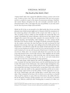
7 The kind of surface that is produced by the operation depends on the shape of the tool and the path it traverses through the materials. When the workpiece is rotated about an axis and the tool is traversed in a definite path relative to the axis, a surface of revolution is generated. When the tool path is parallel to the axis, the surface generated is a cylinder as in straight turning ( ) or boring ( ) operations. Similarly, planes may be generated by a series of straight cuts without rotating the workpiece as in shaping and planning operations ( ). In shaping the tool is reciprocating and the work piece is moved crosswise at the end of each stroke. Planning is done by reciprocating the workpiece and crosswise movement is provided to the tool. Surface may be machined by the tools having a number of cutting edges that can cut successively through the workpiece materials.
8 In plane milling, the cutter revolves and moves over the work piece as shown ( ). The axis of the cutter is parallel to the surface generated. Similarly in drilling, the drill may turn and be fed into the workpiece of the workpiece may revolve while the drill is fed into it ( ). The machine tools, in general, provide two kinds of relative motions. The primary motion is responsible for the cutting action and absorbs most of the power required to perform the machining action. The secondary motion of the feed motion may proceed in steps or continuously and absorbs only a fraction of the total power required for machining. When the secondary motion is added to the primary motion, machine surfaces of desired geometric characteristics are produced.. Consider a situation where both the cutting motions as well as the feed motion (provided at the end of each stroke) are rectilinear but perpendicular to each other.
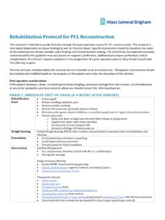
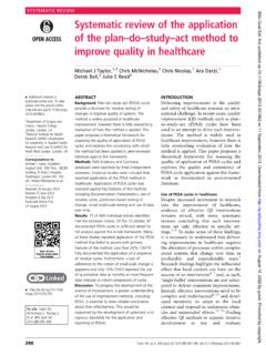
9 Here the machined surface produced is a plane. The line generated by the primary motion (cutting motion) is called the generatrix, while the line representing the secondary motion (feed motion) is called the directrix (Fig. 6a). Depending upon the shapes of the generatrix and the directrix and their relative orientation various geometries can be produced on the workpiece. Consider another case when the generatrix is a circle and the directrix is a line perpendicular to the plane of the generatrix. It is clear that in this situation the surface produced will be a cylinder (Fig. 6b). A tapered surface can be produced by merely changing the angle that the directrix makes with the plane of the generatrix. When the directrix is in the plane of the circular generatrix (Fig. 6c), lines are generated which results in a plain surface when a number of generatrices and directrices are placed side by side in the direction perpendicular to the plane of the generatrix.
10 In actual practice, the cutting is performed by cutting edge and not a point. Thus, a series of generatrix directrix combinations are involved and the relative motion produces a surface rather than a line. Basically there are two methods of producing new surfaces, the tracing method and the generation method. In the tracing method the surface is obtained by direct tracing of the generatrices and when the surface produced is the envelope of the generatrics the process is known as generation. Figs. 6(a) & 6{b), the plane and the cylindrical surfaces are obtained by direct tracing, while in Fig. 6(c) the final surface geometry is the envelope of the generatrices. Manufacturing Processes I Page - 3 ME - LABORATORY Fig. 1 Straight turning Fig. 2 Straight boring Fig. 3 Shaping and planning Fig. 5 Drilling Concept of generatrix and directrix. (a) Rectilinear generatrix and directrix.}