Transcription of LABORATORY SPACE PRESSURIZATION CONTROL …
1 July 12, 2001 11:57 AMDale T. Hitchings, PE, CIH is president of SAFELAB Corporation His firm specializes in laboratoryplanning, safety, and design; industrial ventilation; and indoor air quality consulting. He received is BSME from Northwestern University in 1981 and is a Registered Professional Engineer and a Certified IndustrialHygienist Mr. Hitchings is an ASHRAE member and Chairman of the LABORATORY Systems technicalcommittee 1 LABORATORY SPACE PRESSURIZATIONCONTROL SYSTEMSDale T. Hitchings, PE, CIHINTRODUCTION:Maintaining the proper differential pressure in LABORATORY spaces is one of the mostchallenging tasks facing the LABORATORY environmental CONTROL engineer. Some of theitems which need to be addressed when designing a SPACE PRESSURIZATION controlsystem are: Hazard Assessment Constant-volume vs. VAV Systems Differential Pressure vs. Differential Volume Systems Negative vs.
2 Positive Pressure Requirements CONTROL Signal to Noise Ratio CONTROL Stability and Speed of Response Failure Mode Analysis Building Construction impact on SPACE pressure CONTROL Duct Leakage impact on SPACE pressure controlLaboratories and clean rooms may require that a differential pressure be maintainedbetween them and the adjoining spaces. This requirement may come from codeconsiderations or from the operational requirements of the SPACE . For example, NFPA-45 states that LABORATORY work units and LABORATORY work areas in which hazardouschemicals are being used shall be maintained at an air pressure that is negative relativeto the corridors or adjacent non- LABORATORY 1 This is to prevent the migration ofJuly 12, 2001 11:57 AMPage 2fire, smoke and chemical releases from the LABORATORY SPACE . Labs containing radiationhazards or biohazards may also be required by different agencies to maintain anegative pressure to contain these hazards. Clean Rooms , on the other hand, arenormally operated at a positive static pressure to prevent infiltration of if your building codes and regulatory agencies do not require PRESSURIZATION youmay wish to include this feature in your facility anyway for the reasons described STRATEGIES:The desired result of all SPACE PRESSURIZATION CONTROL systems is to CONTROL the infiltrationinto or the exfiltration out of a SPACE .
3 SPACE PRESSURIZATION CONTROL strategies can bedivided into two major categories: passive and constant-volume laboratories a passive method involves simply balancing thesystem so that the desired SPACE PRESSURIZATION is achieved. This method has seriouslimitations which should be considered carefully before choosing to design a constant-volume system with passive SPACE PRESSURIZATION CONTROL . This type of system willwork only if: 1) all fume hoods remain on and at constant speed or volume at all times,2) no exhaust sources ( hoods) are added or removed, 3) the offsets are largeenough to mask changes in exhaust and supply system performance caused by filterloading, etc., 4) the system is tested and balanced frequently to design conditions, and5) the system is adequately maintained. If you cannot guarantee (or even desire) allthese restrictions then this design approach is inappropriate for your active method for use in a constant-volume LABORATORY involves the utilization ofpressure-independent, constant-volume CONTROL devices in the exhaust and supply ductsJuly 12, 2001 11:57 AMPage 3to actively and dynamically adjust the flowrates to keep them constant and decoupledfrom system static pressure labs require active methods to CONTROL SPACE pressure due to the continuouslychanging exhaust volume from the fume hoods and other exhaust sources.
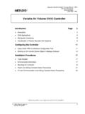
4 Active VAVspace differential pressure CONTROL methods may be subdivided into two types: puredifferential pressure measurement/ CONTROL ( P) and differential volume or flow-tracking( V).DIFFERENTIAL PRESSURE SYSTEMS:The P method of SPACE static pressure CONTROL is relatively straightforward and aschematic of it is shown in Fig. 1. In this method, the differential pressure is controlledwith a differential pressure sensor and a controller and the supply air volume is simply afunction of the P, the setpoint, and the PID constants and . Another similarmethod of static pressure CONTROL utilizes the Bernoulli principle which states that apressure gradient will accelerate a fluid to a velocity proportional to the square root ofthe pressure differential. These pseudo- P systems utilizes an air velocity probemounted in a tube inserted into a hole in the wall between the controlled SPACE and thereference SPACE . The differential pressure will induce air to flow through the tube andthe velocity of the air is sensed by the velocity probe.
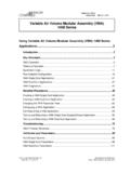
5 A controller then varies thesupply air volume to the LABORATORY to maintain a velocity pressure SYSTEMS:The V method of SPACE PRESSURIZATION CONTROL utilizes analog or digital electroniccontrols to measure the real-time variables and solve the dynamic air balance typical V system is shown in Fig. 2. The exhaust volume is either measured afterJuly 12, 2001 11:57 AMPage 4convergence into a manifold or the individual sources are measured and summed asshown. The supply volume is then controlled (tracked) to achieve the offset. The offsetis the desired infiltration or exfiltration in CFM. A negative offset will reduce the supplyvolume below the exhaust volume and will result in a negative SPACE pressure. Apositive offset will increase the supply volume above the exhaust volume and will resultin a positive SPACE pressure. Although the equation in Fig. 2 implies that the offset is aconstant, in practice, it is a variable. As the volume sensors drift in accuracy, the actualoffset will change.
6 It is necessary to choose an offset that is large enough tocompensate for tight vs. loose envelope construction, duct leakage, and the accuracy ofthe flow measuring devices. You should choose an offset using Equation = 2 S Fmax Equation 1. Where: = instrument error in % full scale or % of readingS = safety factor: depends on tightness of envelope, amount of unmeasured duct leakage and degree of LABORATORY hazard present; recommended range: 0. 5 - 2. 0 Fmax = design maximum exhaust or supply flowrate, whichever is greaterThis will assure (if the safety factor is greater than 1) that under worst case conditionsyou still have some actual offset in the desired direction of flow. For example, in anegatively pressurized lab, the exhaust flow rate will be higher than the supply flow rate,so the Fmax is the maximum exhaust volume. If Fmax is 5000 CFM, is 5% ( ), and Sis 110% ( ) then the Offsetdesign = (2)(.)
7 05)( )(5000) = 550 CFM. Therefore,the worst case scenario would be a system where the exhaust volume reading is 5%below actual, and the supply volume reading is 5% above actual, giving a total airflowerror of +500 CFM. If the design offset is -550 CFM then the actual offset will be -50 July 12, 2001 11:57 AMPage 5 CFM. Normally, airflow errors are random and will tend to cancel. In large labs withmultiple flow measuring instruments, you would expect the total error to be less than themaximum cited in the example. If this is the case, and there is minimum duct leakage,the LABORATORY envelope is very tight, and the LABORATORY hazard is low, then a safetyfactor less than 1 may be appropriate. In any case, verification of actual operating P sand tuning of lab offsets should be done at a predetermined frequency based on thelevel of hazard in the LABORATORY . A maximum of six months between offset calibrationsis SYSTEMS:In laboratories containing extremely toxic or infectious agents such as Biosafety Level 3or 4 laboratories, it may be prudent to utilize both a P and a V system to assure thatan adequate differential pressure is maintained at all times.
8 The most common way ofdoing this is to design a basic V system as previously described, and add a Psensor and controller which is used to reset the V system offset. Here, the long timedelays required to produce an accurate average do not affect the speed of response ofthe system. The P system can dynamically calculate an appropriate offset. As thecharacteristics of the room change, such as duct leakage and envelope tightness, theoffset will change (it usually grows) to maintain the desired LABORATORY SPACE the offset has grown to a predetermined value it may be necessary to recalibrateflow measuring instruments, seal ductwork, or seal bypasses in the LABORATORY envelopeto bring the system back into specification. Monitoring the offset in a hybrid system ofthis type is a good way to monitor the integrity of the total duct/ CONTROL /envelope 12, 2001 11:57 AMPage 6 STABILITY vs. SPEED OF RESPONSE: P and pseudo- P CONTROL schemes have certain characteristics which thedesigner/owner needs to be aware of.
9 A reasonable pressure differential to maintainusing normal construction techniques is approximately water gauge ( ) To putthis into perspective, = PSI. This is an extremely small pressuredifferential (signal) to measure and providing adequate calibration for the instrument isalso difficult. The fluctuations (noise) in this signal, which are caused by the openingand closing of doors, people traffic, elevators, stack effects and atmosphericdisturbances like wind, are on the order of This represents a signal to noiseratio of approximately 1 trying to determine the level of a lake to within an inch when the waves are afoot high. To do so, it would be necessary to average out the wave crests and can be done, but it takes time. If you want great accuracy you have to average over along period of time. If you need to respond quickly to the signal then you can t be asaccurate. Accuracy and speed or response are in direct conflict. For true stability in a P system, the response time is usually measured in minutes.
10 Therefore, many ofthese systems and instruments sacrifice stability for speed and can oscillate about thesetpoint for quite some time before settling down to stable CONTROL . Unfortunately, thissettling down period is often greater than the frequency of upsets and the controlleddevice may oscillate all day long until everyone goes P systems which measure the air velocity are somewhat faster and morestable because the velocity signals and noise are proportional to the square root of thedifferential pressure. This improves the signal to noise ratio to approximately 1:3. Thissimple change in the measured variable improves the system performance by a factorJuly 12, 2001 11:57 AMPage 7of three. However, the noise is still about three times as large as the signal and you stillmay wait as long as 60 seconds for marginally stable output after an upset in the spacepressure. The performance of this type of equipment varies from manufacturer tomanufacturer and care should be exercised when selecting them for your undesirable characteristic of both of these pressure measuring devices is thatthe measured variables (pressure or velocity) totally disappear when the LABORATORY dooris opened.