Transcription of Large Loop Antennas
1 Chapter 1 2/9/2005, 1:21 PM CHAPTER 10 CHAPTER 10 Large Loop Antennas The delta-loop antenna is a superb example of a high performance compromise antenna. The single-element loop antenna is almost exclusively used on the low bands, where it can produce low-angle radiation, requiring only a single quarter-wave high support. We will see that a vertically polarized loop is really an array of two phased verticals, and that the ground requirements are the same as for any other vertically polarized antenna.
2 This means that with low delta loops, the horizontal wire will couple heavily to the lossy ground and induce significant losses, unless we have improved the ground by putting a ground screen under the antenna. (See Chapter 9, Section and Section 2.) I have seen it stated in various places that delta loops don t require a good ground system. This is as true as saying that verticals with a single elevated radial don t require a good ground system. Loop Antennas have been popular with 80-meter DXers for more than 30 years.
3 Resonant loop Antennas have a circum ference of 1 . The exact shape of the loop is not particularly important. In free space, the loop with the highest gain, how ever, is the loop with the shape that encloses the largest area for a given circumference. This is a circular loop, which is difficult to construct. Second best is the square loop (quad), and in third place comes the equilateral triangle (delta) loop (Ref 677). The maximum gain of a 1- loop over a /2 dipole in free space is approximately dB. Delta loops are used exten sively on the low bands at apex heights of /4 to 3 /8 above ground.
4 At such heights the vertically polarized loops far outperform dipoles or inverted-V dipoles for low-angle DXing, assuming good ground conductivity. Loops are generally erected with the plane of the loop perpendicular to the ground. Whether or not the loop produces a vertically or a horizontally polarized signal (or a combina tion of both) depends only on how (or on which side) the loop is being fed. Sometimes we hear about horizontal loops. These are Antennas with the plane of the loop parallel to the ground. They produce horizontal radiation with takeoff angles determined, as usual, by the height of the horizontal loop over ground.
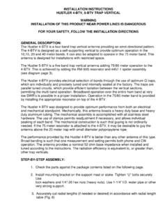
5 1. QUAD LOOPS Belcher, WA4 JVE, Casper, K4 HKX, (Ref 1128), and Dietrich, WA RDX, (Ref 677), have published studies com paring the horizontally polarized vertical quad loop with a dipole. A horizontally polarized quad loop antenna (Fig 10-1A) can be seen as two short, end-loaded dipoles stacked /4 apart, with the top antenna at /4 and the bottom one just above Fig 10-1 Quad loops with a 1- circumference. The current distribution is shown for (A) horizontal and (B) vertical polarization. Note how the opposing currents in the two legs result in cancellation of the radiation in the plane of those legs, while the currents in the other legs are in-phase and reinforce each other in the broadside direction (perpendicular to the plane of the antenna).
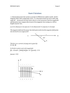
6 Large Loop Antennas 10-1 Chapter 2 2/9/2005, 1:21 PM Fig 10-2 Radiation resistance and feed-point resistance for square loops at different heights above real ground. The loop was first dimensioned to be resonant in free space (reactance equal to zero), and those dimensions were used for calculating the impedance over ground. At A, for horizontal polarization, and at B, for vertical polarization. Analysis was with NEC at MHz. ground level. There is no broadside radiation from the vertical wires of the quad because of the current opposition in the vertical members.
7 In a similar manner, the vertically polarized quad loop consists of two top-loaded, /4 vertical dipoles, spaced /4 apart. Fig 10-1B shows how the current distribution along the elements produces cancellation of radiation from certain parts of the antenna, while radiation from other parts (the horizontally or vertically stacked short dipoles) is reinforced. The square quad can be fed for either horizontal or vertical polarization merely by placing the feed point at the center of a horizontal arm or at the center of a vertical arm.
8 At the higher frequencies in the HF range, where the quads are typically half to several wavelengths high, quad loops are usually fed to produce horizontal polarization, although there is no specific reason for this except maybe from a mechanical standpoint. Polarization by itself is of little importance at HF (except on 160 meters! See Chapter 1), because it becomes random after ionospheric reflection. Impedance The radiation resistance of an equilateral quad loop in free space is approximately 120 . The radiation resistance for a quad loop as a function of its height above ground is given in Fig 10-2.
9 The impedance data were obtained by modeling an equilateral quad loop over three types of ground (very good, average and very poor ground) using NEC. MININEC cannot be used for calculating loop impedances at low heights (see Section ). The reactance data can assist you in evaluating the influence of the antenna height on the resonant frequency. The loop antenna was first modeled in free space to be resonant at MHz and the reactance data was obtained with those free-space resonant-loop dimensions. For the vertically polarized quad loop, the resistive part of the impedance changes very little with the type of ground under the antenna.
10 The feed-point reactance is influenced by the ground quality, especially at lower heights. For the hori 10-2 Chapter 10 zontally polarized loop, the radiation resistance is noticeably influenced by the ground quality, especially at low heights. The same is true for the reactance. Square Loop Patterns vertical polarization The vertically polarized quad loop, Fig 10-1B, can be considered as two shortened top-loaded vertical dipoles, spaced /4 apart. Broadside radiation from the horizontal elements of the quad is canceled, because of the opposition of currents in the vertical legs.