Transcription of Laser Interferometry - California Institute of …
1 Ph 3 - INTRODUCTORY PHYSICS LABORATORY California Institute of Technology Laser Interferometry1 IntroductionThe purpose of this lab is for you to learn about the physics of Laser Interferometry and the science of precisionmeasurements, and for you to gain some laboratory experience with optics and electronic test equipment along theway. You will build and align a small Laser interferometer in the Ph3 lab, you will determine how accurately you canmeasure distance using this interferometer, and then you will use the interferometer to examine the small motions ofan oscillating mechanical InterferometryIn this experiment you will be building a basic Michelsoninterferometer (named after Albert Michelson, who in-vented it in the late nineteenth century).
2 While optical Interferometry can be done using broad-band light sources (asMichelson did long before lasers were invented), it is much easier with a nearly monochromatic light source like alaser. You will be using the optical layout shown in Figure basic idea is fairly simple: the initial Laser beam is split into two equal-intensity beams by the beam splitter,these beams both reflect off their respective end mirrors, and the beams recombine once again at the much light ends up going into the detector depends on the relative phase of the recombining beams. If thebeams are in phase, then we say they combineconstructively, and in this case the beams add and the full initial laserbeam intensity lands on the detector.
3 But if the beams are out of phase, then they combinedestructively,sonolightlands on the detector. If we translate one of the end mirrors as shown in Figure 1, then small changes in the mirrorposition can be measured by the changing light intensity on the detector. Laser Interferometry is a sensitive way ofmeasuring small displacements, and it is a non-contact measurement that can operate over quite large understand how the interferometer works in detail, we have to look at the math. If we approximate ourGaussian Laser beams as plane waves, then we can write the electricfield of a propagating light wave as ( )= 0 ( )where 0is a constant, =2 is the angular frequency of the light, =2 is the wave number, and isthe light wavelength.
4 Here we have defined our coordinates so that the Laser beam is propagating in the will be using a Helium-Neon Laser , which puts out red light with = 633nm, so the oscillation frequency ofthe electricfield is = 2 = 4 7 we have no electronics that can operate at 470 THz, we do not measure any electricfields when we areworking with visible light. Instead we measure the power in a beam, which is proportional to the square of theelectricfield averaged over time, and we write this as 0= 20where is a proportionality constant. For the laseryou will be using, the initial power of the Laser beam is about 0=2milliWatts, which is about what you get from aweak Laser brief word about Laser safety.
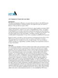
5 A good rule-of-thumb to remember is that staring directly at the sun puts about1 mW into each of your eyes, so a 2 mW Laser beam is enough to cause eye damage, at least in principle. But thisonly happens if you stare directly into the beam for at least a second or two, and this is all but impossible to do byaccident. Thus a 2 mW visible Laser (like a Laser pointer) is quite safe to work a key point in Interferometry is that when the beams recombine at the beamsplitter, they do so by addingPage 1 Figure 1. The optical layout of a basic Michelson interferometer. Light from the source (a He-Ne Laser in ourcase)first strikes a 50:50 beamsplitter that splits the lightinto two equal-intensity beams.
6 These beams travelthe down the arms of the interferometer, where they are then reflected back by two mirrors. The beams recom-bine back at the beamsplitter, so some of the light is directed toward the detector while some is reflected backtoward the source. The intensities of these two beams (one going toward the detector and the other shining backtoward the Laser ) depend on the path length difference 1 2of the two arms of the interferometer. (Image )their electricfields, and adding electricfields is not the same as adding powers. To see this, write the electricfield ofthe recombined beam going toward the detector as (leaving off some of the extraneous factors for now) det( 1 2)
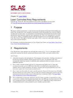
7 02 1+ 02 2 Thefirst term in this expression represents the beam that traveled down thefirst arm and back, a total distance 1 picking up the phase factor 1, while the second term represents the second beam that traveled a distance 2 Rewriting this det 02 1+ 1where = 2 1is the path difference between the two arms, we then take the absolute square to get the powerhitting the detector det | det|2 204 1+ 2 204 1+ 1+ + 204[1 + cos( ) sin( )] [1 + cos( )+ sin( )] 204[2 + 2 cos( )]If we do this carefully to get all the factors of two right, then the power hitting the detector becomes det= 02[1 + cos( )](1)We could do the same calculation for the light that ends up going back toward the detector (the other path throughthe beamsplitter; see Figure 1), and this would give back to source= 02[1 cos( )]Page 2 Figure 2.
8 A plot of the power hitting the detector for an ideal interferometer, divided by the initial Laser power 0 as a function of the displacement of the translating mirror divided by the light wavelength The interferometer ismost sensitive to small changes in at the points shown, when det= 0 2 Adding these two paths gives 0 which just means that energy is being 2 shows a plot of det 0as a function of for this ideal interferometer, where = 2is thedisplacement of the translating mirror. (The path length change is equal to2 because the beam travels to themirror and back again.)
9 Note that detgoes from a minimum of zero, when the cosine term equals minus one, to amaximum of 0when the cosine equals 2 is the most important plot in this experiment, so make sure you understand what it means. If not, asksomeone about you go into the lab and start playing with optics, let s take a closer look at how the interferometer shownin Figure 1 gets translated into a real experiment. We use a photodetector (a photodiode and some amplifyingelectronics) to convert the incident optical power to a voltage detthat is proportional to det, converting the opticalpower det(in milliwatts) to a measured voltage det(in volts).
10 Also, in an real interferometer the two beams to notrecombine perfectly, so the light intensity does not go all the way to zero as given in Equation 1. Putting all thistogether, the actual detector voltage becomes det=12( max min)[1+cos(2 )] + min(2)where we have written this so that detgoes from a minimum minto a maximum max If you want to measure large displacements with using an interferometer, then you can do so by countingdark/light cycles as you translate the mirror. Our focus here will instead be on measuring very small displacements and in the lab we will see just how small.