Transcription of Lateral buckling of steel plate girders for bridges …
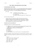
1 63 STRUCTURES1. IntroductionAn important part of the design of a steel concrete composite bridge is the stability check of the girders during construction of the concrete slab and prior to it hardening, whereupon it provides continuous restraint to the top flange. This may be a critical check as the girders will often be most susceptible to Lateral torsional buckling (LTB) failure when the deck slab is being poured. Beams are normally braced in pairs with discrete torsional restraints, often in the form of X bracing or K bracing (as shown in Figure 1), but for shallower girders single horizontal channels connecting the beams at mid-height is an economic, but less rigid, girders with torsional bracing generally fail by rotation of the braced pair over a span length as shown in Figure 2. With widely spaced torsional bracing, buckling of the compression flange between bracing points is also possible.
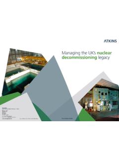
2 It was once thought that torsional bracing was effective in limiting failure to occur by buckling of the compression flange between restraints but this is now known not to be so and is reflected in the calculation method given in BS 5400:Part 3:20001. FIGURE 1. BRACED BEAMS IN PAIRS PRIOR TO CONCRETINGA bstractSince publication of BS 5400:Part 3:2000, the design check of paired plate girders during erection has become more onerous in the UK. This has led to increases in top flange size or the provision of plan bracing just for the erection condition where previously neither modification to the permanent design was likely to be needed. This change has been brought about by the addition of two main features in BS 5400:Part 3:2000; a change to the mode of buckling considered in deriving the girder slenderness and the addition of more conservative buckling curves when the effective length for buckling differs from the half wavelength of buckling .
3 The latter change was incorporated because of concerns that the imperfection over the half wavelength was more relevant than that over the effective length which is implicit in traditional strut curves. BS EN 1993 Part 1-1 requires no such reduction in resistance and the work in this paper was prompted by a proposal to modify the rules of BS EN 1993-2 for bridges in the UK s National Annex to be more like those in BS 5400:Part 3. The authors believed this to be paper investigates buckling cases where the effective length for buckling is shorter than the half wavelength of buckling and demonstrates that the series of correction curves use in BS 5400:Part 3:2000 are unnecessary and that the BS EN 1993-1-1 method is satisfactory and slightly conservative. The paper also outlines the design process to BS EN 1993 using both elastic critical buckling analysis and non-linear analysis.
4 The case studies considered are a simple pin-ended strut with intermediate restraints, a pair of braced girders prior to hardening of the deck slab and a half-through deck with discrete U-frame restraints. For the latter two cases, the results predicted by BS 5400:Part 3 and BS EN 1993-1-1 are compared with the results of non-linear finite element buckling of steel plate girders for bridgeswith flexible Lateral restraints or torsional restraintsHighways & TransportationAtkinsEpsom, UKHighways & TransportationAtkinsEpsom, UKHead of Bridge Design and TechnologyDesign EngineerMA (Cantab) CEng FICEMA (Cantab) MEngChris R HendyRachel P JonesMain 63 Main 6303/03/2009 15:50:4903/03/2009 15:50:4964 STRUCTURES022 The previous incorrect approach however allowed girders to be constructed safely for many years, probably due to incidental bracing arising from frictional restraint of the formwork and because of partial factors used in design.
5 The mode shown in Figure 2 is however prevented by adding plan bracing to the compression flange (which is effectively provided by the deck slab once it hardens) and the latter mode ( buckling of the flange between bracings) then occurs. If the check of the paired beams during concreting suggests inadequacy, either the compression flange has to be increased in size or plan bracing added. Plan bracing is not a popular choice with contractors in the UK. If the bracing is placed above the top flange for incorporation within the slab, it interferes with reinforcement fixing and the permanent formwork. If it is placed to the underside of the top flange, it presents both a long term maintenance liability and a short term health and safety hazard during its erection. It is often therefore preferred to increase the width of the top flange or provide more discrete torsional 2.
6 buckling OF PAIRED BEAMS PRIOR TO CONCRETE HARDENINGThe calculation of buckling resistance for the construction condition is currently both lengthy and conservative to BS 5400:Part 3:2000. This has the consequence that frequently the check is not carried out properly at the tender stage of a project. When the check is subsequently carried out at the detailed design stage, it is often found to require additional bracing or changes to plate thickness. One of the reasons for this is that the current BS 5400:Part 3 method is too design method for beams with discrete torsional restraints (the construction condition above) in BS 5400:Part 3:2000 (and BD 13/062) is very conservative for a number of reasons as follows:(i) The use of multiple strength-slenderness curves for different le/lw ratios, which take the imperfection appropriate to the half wavelength of buckling , lw, (typically the span length) and apply it to the shorter effective length, le, is incorrect and this is demonstrated in the remainder of this paper.
7 (ii) The calculation of effective length for the true buckling mode is simplified and conservative. To overcome this, an elastic critical buckling analysis can be performed to determine the elastic critical buckling moment and hence slenderness. This technique is used later in this paper.(iii) The curves provided to relate strength reduction factor to slenderness, which are derived for strut buckling , are slightly conservative for a mode of buckling where the paired girders buckle together by a combination of opposing bending vertically and Lateral bending of the flanges.(iv) Incidental frictional restraint from formwork is first of these issues is studied in the remainder of this paper and it is shown that the current multiple strength-slenderness curves for different le/lw ratios in BS 5400:Part 3 are incorrect and overly conservative.
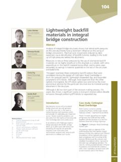
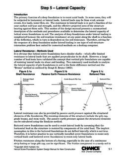
8 This conclusion applies both to the construction condition above and to beams with U-frame support to the compression flange, since both cases produce an effective length that is less than the half wavelength of buckling . Non-linear analysis is used to illustrate this buckling curvesThe buckling curves in BS 5400:Part 3:2000 are based on a pin ended strut with the half wavelength of buckling equal to the effective length of the strut. The resistance is dependent on the initial geometric imperfection assumed and the residual stresses in the section. The equivalent geometric imperfection implicit in these equations is not constant but is slenderness-dependent (and therefore a function of effective length) in order to produce a good fit with test results. The buckling curves in BS 5400:Part 3:2000 for beams with intermediate restraints are modified based on the ratio between the effective length, le, and the half wavelength Lateral buckling of steel plate girders for bridgeswith flexible Lateral restraints or torsional restraintsFIGURE 3.
9 BD 13/06 buckling CURVES (FOR WELDED MEMBERS)Main 64 Main 6403/03/2009 15:50:5003/03/2009 15:50:5065 STRUCTURES0223. buckling cases investigatedTo investigate the validity of the BS 5400:Part 3 approach for beams with Lateral restraints, a number of situations were considered. First, to clarify the principles involved, a pin-ended strut with springs providing Lateral restraints was considered. The behaviour of this simple model, axially loaded and with an initial geometric imperfection, was compared to the behaviour of an equivalent strut with no Lateral restraints but the same elastic critical buckling load. Second, two practical situations where a reduction in capacity to BS 5400:Part 3 would be required due to differences between the half wavelength of buckling and the effective length were considered.
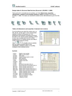
10 These were a typical half-through bridge with U-frames and a steel -concrete composite bridge during Simple strut model Figure 5 illustrates two struts with identical elastic critical buckling loads; one with flexible intermediate transverse restraints and the other without. BS 5400:Part 3 and BD 13/06 would predict the case with intermediate restraints to have the lower ultimate resistance (as distinct from elastic critical buckling load) because it has a ratio of le/lw < The comparison of true ultimate strength in the two cases was buckling , lw. This was considered necessary in order to factor up the imperfection to be used in the buckling curve from that appropriate to the effective length to that appropriate to the half wavelength of buckling . BS 5400:Part 3 gives rules for calculating le where Lateral restraints to the compression flange, torsional restraints, discrete U-frame restraints or restraint from the bridge deck are provided.