Transcription of Lathe Milling Attachment - Vintage Projects and …
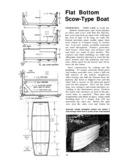
1 Lathe Milling AttachmentBy L C. MASONM illing Attachment inuse on 7-in. Lathe formilling out parts inthe manifold of amodel 4-cylinder gasengine. One holdingclamp removed CLEVERLY stacking cold-rolled flat stocktogether, T-slots and slide for this lathemilling Attachment are made without costlymachinery. In fact, only two tools, a drill pressand Lathe , are needed to make the mounted on the cross slide of a Lathe (Fig. 1), the Attachment features a swivel baseand tilting slide which has T-slots for clampingthe work securely in place. Although this at-tachment was made for a 7-in. Atlas Lathe , theoverall dimensions could be increased 25% foruse with a 9 or 10-in by cutting the stock size cold-rolled flatstock for T-slot pieces A, B, C and D in Fig. 3to 3-in. lengths. Then lay out and drill the #21holes. Pieces A and B, and C and D can beclamped together when drilling so that they willline up properly when assembling later.
2 Next,hacksaw the slide plate E in Fig. 3 to shape andtrim up the cut edges with a file. Lay out andscribe lines on the slide plate for locating piecesB and D. Be sure these lines are square withthe sides of the slide plate. Clamp the B and Dpieces to the slide plate and drill the 12 #21holes. Then open the holes with a #9 drill andcountersink the holes on the back of the slideplate to sink 10-32 fh screws just below thesurface. Tap the #21 holes in pieces A and Cwith 10-32 NF cut the back plate pieces (F and G inFig. 3) to length. Since stock size cold rolled120does not come 2 3/16 and 1 11/16 in. wide, youwill have to machine them. Clamp them on thelathe faceplate with a 90 angle block and turnthe 2 3/16-in. piece about 1/64 in. undersize. Setthese pieces aside for the moment, and make upand drill pieces H, J and K in Fig.
3 3. Notethat the ends of piece H are filed to take thebrass gib L, which should also be made up atthis assemble, first clamp piece J to the backand right side of the slide plate. The top andbottom screws securing piece J will run intothe B pieces, so bolt these pieces on the frontof the slide plate. Spot drill the slide platethrough the #9 holes in piece J, then remove itand drill through with a #21 drill. Tap be certain of getting piece H parallel withpiece J, place piece F between them. Be surethat the gib, piece L, is between pieces H andF also. Clamp piece H to the slide plate and testpiece F to see that, it slides up and down smooth-ly. Then spot drill the slide plate through theholes in piece H and drill and tap as you didfor piece J. Assemble the K pieces with the Fpiece in , place piece G, the other back plate youmachined to 1 11/16 in.
4 Wide, on piece F betweenthe K pieces. There should be 1/32 in. clearanceon each side between the K pieces. Clamp theG piece in place, and drill the 3/16 in. rivet holesdeep enough to spot drill the hole locations onSCIENCE AND MECHANICSthe F piece. Then remove the pieces andcontinue drilling the holes through theF piece. Countersink the rivet holes onthe F and G pieces a good 1/16 in. andfasten with rivets cut from 3/16 in. steel rod. Heat rivets red hot beforesetting. When cool, file or grind flush atboth next step is to true up the front,or top surfaces of the T-slot pieces A and Cso that they will be parallel with part G ofthe back plate that fastens to the angle onthe Lathe cross slide. First remove piecesH, J and K on the back of the slide permanently fasten T-slot pieces A,B, C and D to the slide plate.
5 File pro-jecting 10-32 screws flush with A and Cpieces. Reassemble the riveted back plateto the slide with pieces H, J, K and the screws so that the back platewill not slide. Now clamp the assemblyto the Lathe faceplate, so that the backplate is against the faceplate and T-slotpieces facing outward. Take a series oflight cuts off the surfaces of pieces A andC, which will true up the front and com-pensate for any difference in the thick-nesses of the flat bar the feed screw, make up piece Min Fig. 3 and fasten to the top of theslide plate with two 10-32 fh screws as inFig. 2. Do not drill the -in. hole in pieceM at this time. Also make the nut, pieceN in Fig. 3, and fasten to the top of pieceG with two 10-32 fh the holes for the feed screwthrough pieces M, N and the back platemust be aligned and parallel with the slideways, clamp the assembly in the uprightposition on the drill press table so thatthe front of the slide plate and right sideof the slide way is parallel with the drillbit.
6 If the drill press has a tilting table, besure to square the table with the drill bitfirst. Using a #21 drill, bore a holethrough piece N and M, and into the backplates about in. in depth. The holeshould land right between the riveted backplates. Remove the #21 drill, chuck a -in. drill and bore through piece M , without removing the assembly fromits clamped position on the drill press table,take off pieces M and N and bore a 9 3 5/8 in. deep into the riveted backplates. While you have piece N off tap the#21 hole with 10-32 threads and reassem-ble to the back the feed screw, O in Fig. 3, from3/8-in. steel rod, reducing the thread littleby little until you have a shakeless fit withthe nut. Note that the other end of thescrew is threaded -28 for the handle anddial. Turn the dial, P in Fig. 3, and scribethe graduations on the bevel with a screw-cutting tool bit turned sideways in the121'tool holder set at center height.
7 Twenty-five divisions on the dial will indicate slidemovement of .002 in. for each division. A25-tooth gear fastened on the Lathe spindlewas used for indexing. Scribe every fifthline (.01) the full width of the bevel. Makethe handle pieces Q and R as detailed inFig. 3, and turn the thrust washers frombronze or assembling the feed screw to theslide and back plate, turn the mountingbolt 5 in. (Fig. 3). Use a stock -20 with the bolt. Then remove the backplate from the slide and bore the , countersinking the widest of the backplates to the same taper as on the mount-ing bolt. Try to arrange the work so thatthe taper on the bolt and back plate canbe turned without changing the angle ofthe Lathe compound assembling the feed screw to bear-ing block M on the slide plate, place athrush washer on the feed screw shaft ateach side of block M.
8 Then screw on thedial and handle on the feed screw, allow-ing just enough play for easy the handle and dial locked togetherlike locknuts, hand solder or braze thehandle to the dial. Drill a 1/16-in. holethrough the handle and feed screw anddrive a pin through it. Scribe an indexmark on the slide plate as on E in Fig. assembling the mounting bolt tothe back plate, file notches in the boltheads as in Fig. 3. Then, after insertingthe bolt in the back plate, raise burrs witha centerpunch at the edge of the hole tofill the filed notch. This will keep the boltin place and prevent its turning. Nowplace the back plate in the slide ways,engage the feed screw and work it backand forth a few times to test the slideways. If the K pieces are too tight, placea paper shim under each for clearance.
9 Iftoo loose, file or grind down the thicknessof pieces H and J. Adjust the gib screwsfor a smooth sliding fit without completed Milling Attachment mountson a 3-in. length of 3/8 x 3 x 3-in. angle ironbolted to Lathe cross slide in place of thecompound rest as in Fig. 1. The size ofthis angle iron will vary depending uponthe make and: model of the Lathe it is tobe used with. Regardless of the size ofangle iron needed, first face off the twooutside surfaces of the angle by clampingit on the Lathe face plate with an angleblock. Then cut a in. thick steel plateand rivet it to the inside surface of oneleg of the angle as in Fig. 2. Again clampthe angle to the Lathe face plate and borea hole through the angle and -in. platelarge enough to fit on the compoundmounting lug on the Lathe cross the angle iron to the lug in the same122way the compound rest was clamped, drillingand tapping needed holes in angle iron, to takethe plunger pins and clamp screws used tofasten the compound drill the -in.
10 Milling Attachment mountinghole in the angle, clamp it so that the verticalface is exactly at right angles to the Lathe bedways and bore with a drill chucked in the latheheadstock. This will place the pivot point of theattachment on the Lathe centerline which is ad-vantageous for some types of Milling to be milled is clamped against the ma-chined surface of the slide as in Fig. 1. Use in. squarehead machine bolts with headsplaced in T slots for LIST Milling ATTACHMENTAll Dimensions in InchesSize and DescriptionNo. x 5/8 x 4 cold rolled steel x 3/8 x 4 cold rolled steel x x 3 cold rolled steel x 5/8 x 3 cold rolled steel x x 3 cold rolled steel x 1 x 3 cold rolled steel x x 1 cold rolled steel x 3 x 5 7/8 cold rolled steel x 2 x 4 1/8 cold rolled steel x 1 x 4 cold rolled steel3/8 x x 1 cold rolled steel1 dia.