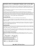
Transcription of LEAD FREE Series 994 - Watts Water Technologies
1 994 OSYM odelsSuffix:NRS non-rising stem resilient seated gate valvesOSY UL/FM outside stem & yoke resilient seated gate valves**OSY FxG flanged inlet gate connection and grooved outlet gate connection **OSY GxF grooved inlet gate connection and flanged outlet gate connection **OSY GxG grooved inlet gate connection and grooved outlet gate connection LF without shutoff valvesS cast iron strainerAvailable with grooved NRS gate valves - consult factory** Post indicator plate and operating nut available - consult factory** **Consult factory for dimensions Note: The installation of a drain line is recommended.
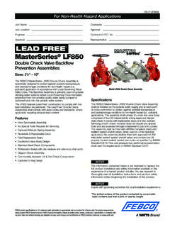
2 When in stall ing a drain line, a 994 AGK-P air gap is necessary. See ES-AG/EL/TC for additional 994Re duced Pres sure Zone AssembliesSizes: 21 2" 10" (65 250mm) Series 994 Re duced Pressure Zone Assemblies are de signed to pro vide pro tec tion of the potable Water supply in ac cor dance with na tion al codes. This Series can be used where ap proved by the local au thor i ty hav ing ju ris dic tion on health hazard cross con nec tions. Se ries 994 fea tures a short lay length, light weight stain less steel body, cor ro sion re sis tant stainless steel re lief valve, and patented tor sion spring check Stainless steel construction provides long term corrosion resistance and maximum strength Stainless steel body is half the weight of com pet i tive designs reducing installation & shipping costs Short end-to-end dimensions makes retrofit easy Bottom mounted relief valve reduces clearance re quire ments when installed against an outside wall Torsion spring check valves provides maximum flow at low pressure drop Thermoplastic & stainless steel check valves for trouble- free operation No special tools required for servicing Compact
3 Construction allows for smaller enclosures Stainless steel relief valve features a balanced rolling diaphragm to eliminate sliding seals and lower maintenance costsSpecificationsA Reduced Pressure Zone Assembly shall be installed at each cross con nec tion to prevent backsiphonage and backpressure of haz ard ous ma te ri als into the potable Water supply. The assembly shall consist of a pres sure differential relief valve located in a zone be tween two pos i tive seating check valves. The main valve body shall be man u fac tured from 300 Series stainless steel for corrosion re sis tance. The check valves shall be of thermoplastic construction with stain less steel hinge pins, cam arm, and cam bearing.
4 The check valve shall uti lize a single tor sion spring design to minimize pressure drop through the as sem bly. The check valves shall be modular and shall seal to the main valve body by the use of an O ring. There shall be no brass or bronze parts used with in the check assembly or relief valve. The use of seat screws to re tain the check valve seat is prohibited. All internal parts shall be ac ces si ble through a single cover on the valve assembly se cure ly held in place by a two bolt grooved coupling. The dif fer en tial relief valve shall be of stain less steel con struc tion and shall utilize a rolling di a phragm and no sliding seals.
5 The relief valve shall be bot tom mount ed and supplied with a steel reinforced sensing hose. The assembly shall include two resilient seated shutoff valves & four ball type test cocks. The assembly shall be a Watts Series AvailableWattsBox Insulated more information, send for literature : INQUIRE WITH GOVERNING AUTHORITIES FOR LOCAL INSTALLATION REQUIREMENTSTest CocksStainless Steel CoverGrooved CouplingDiscReplaceable SeatTorsion SpringLaser Cut/Polished Cam ArmStainless Steel Relief ValveFor Health Hazard ApplicationsES-994 Job Name Contractor Job Location Approval Engineer Contractor s No.
6 Approval Representative Watts product specifications in customary units and metric are approximate and are provided for reference only. For precise measurements, please contact Watts Technical Service. Watts reserves the right to change or modify product design, construction, specifications, or materials with out prior notice and without incurring any obligation to make such changes and modifications on Watts products previously or subsequently sold.* The wetted surface of this product contacted by consumable Water contains less than one quarter of one percent ( ) of lead by weight.
7 LEAD free *Dimensions WeightsStandardsAWWA C511 92, CSA , UL ClassifiedApprovalsApproved by the Foundation for Cross Connection Control & Hydraulic Research at the University of Southern California Sizes 21 2" 6" (65 250mm)MaterialsAll internal metal parts: 300 Series stainless steel Main valve body: 300 Series stainless steel Check assembly: Noryl Flange dimension in accordance with AWWA Class DPressure TemperatureTemperature Range: 33 F 110 F ( C 43 C) continuous Maximum Working Pressure: 175psi ( bar) Series 994 performance as established by an independent testing laboratory (1996 UL)Air Gap AssemblyHorizontal Air Gap Fitting 21 2" 10" Model 994 AGK P2" (50mm) Pipe ThreadDC (open) 21 2" (65mm)PressureFlow ** 6" (150mm)Flow** 3" (80mm)Pressure** 8" (200mm)** 4" (100mm)** 10" (250mm)Flow**Capacity *Typical maximum flow rate ( feet/sec.)
8 **UL rated flowGMLA Size (DN) DiMeNSiONS WeiGhT A C (OSY) C (NRS) D G L M N P w/Gates w/o Gatesin. mm in. mm in. mm in. mm in. mm in. mm in. mm in. mm in. mm in. mm lbs. kgs. lbs. 2 65 37 940 163 8 416 93 8 238 101 2 267 10 254 22 559 10 254 61 2 165 7 178 148 67 60 273 80 38 965 187 8 479 101 4 260 101 2 267 10 254 22 559 101 8 257 7 178 71 2 191 226 103 62 284 100 40 1016 223 4 578 123 16 310 101 2 267 10 250 22 559 121 8 308 81 4 210 9 229 235 107 65 306 150 481 2 1232 301 8
9 765 16 406 111 2 292 15 381 271 2 699 181 2 470 131 2 343 11 279 380 172 110 508 200 521 2 1334 373 4 959 1915 16 506 121 2 318 15 381 291 2 749 215 8 549 151 2 394 131 2 343 571 259 179 8110 250 551 2 1410 453 4 1162 2313 16 605 121 2 318 15 381 291 2 749 26 660 181 2 470 16 406 773 351 189 86NP7" (175mm)113 4" (298mm)Flow Flow 0 100 200 300 400 500 600 gpm 380 760 1140 1520 1900 2280 lpm 15 fps mps0 100 200 300 400 500 600 gpm 380 760 1140 1520 1900
10 2280 lpm 15 fps mps0 100 200 300 400 500 600 700 gpm 380 760 1140 1520 1900 2280 2660 lpm 15 fps mps 0 250 500 750 1000 1250 1500 gpm 950 1900 2090 3800 4750 5700 lpm 15 fps mpsFlow 0 400 800 1200 1600 2000 2400 gpm 1520 3040 4560 6080 7600 9120 lpm 15 fps mps 0 500 1000 1500 2000 2500 3000 gpm 0 1900 3800 5700 7600 9500 11400 lpm 15 fps mps kPa psi 145 21 124 18 103 15 83 12 62 9 41 6 21 3 Pressure