Transcription of LEAFLET YOKOHAMA PNEUMATIC FENDER - Fishing …
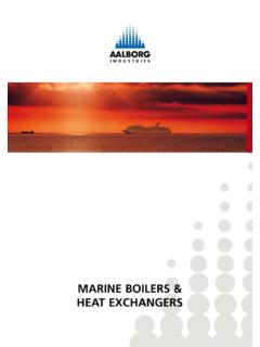
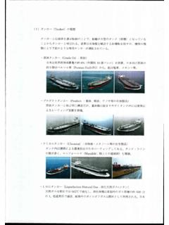
1 LEAFLET . YOKOHAMA . PNEUMATIC . FENDER . INTRODUCTION. The YOKOHAMA PNEUMATIC Rubber FENDER was developed in 1958 based on a rubber company's technology for automobile tires and rubber aircraft fuel tanks. Progress in the development of such floating PNEUMATIC rubber fenders is closely related to the progress and development of ship technology, and has to continuously cope with progressively larger oil tankers such as VLCC's, ULCC's, large gas carriers, bulk carriers and floating structures. Floating PNEUMATIC fenders are used world wide for ship-to-ship ( STS ). transfer operations, terminals, and for all kinds of ships. Since its creation until today, more than 45,000 fenders have been supplied worldwide both for ship-to-ship and ship-to-dock operations serving our valuable customers. These fenders play a critical role in the safe operation of ship berthing and mooring. ship-to-ship ( STS ) operations ship-to-dock ( STJ ) operations YOKOHAMA AIR BLOCK FENDER ( ABF-P ). A YOKOHAMA original style fixed PNEUMATIC FENDER with frontal protector panel model developed in the 1970's, which is another idea PNEUMATIC FENDER system providing a soft and stable.
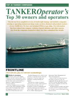
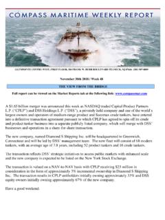
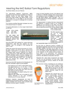
2 Berthing/mooring condition to the ship. The ABF-P is a high performance fixed FENDER system with high robustness preferred in large-scale crude oil and LNG/LPG loading terminals, especially in exposed sea condition. ADVANTAGES. The YOKOHAMA Rubber Co., Ltd. confirms that all its PNEUMATIC Rubber Fenders fully comply with all requirements of ISO17357. 1. Safety and Reliability 120. Relative Reaction Force ( ). 100. Fenders are constructed of several layers of strong tire-cord, 80. and are thus resistant to pressure and cutting. 60. PNEUMATIC 40 Solid Foam 2. No Deterioration or Variation in Performance 20. 0. 1 10 100 1000 10000 100000 1000000. Fenders utilize the compressive elasticity of air, therefore Number of Compression Cycles performance deterioration due to fatigue is absent. 3. Advantages at Inclined Berthing Eenergy absorption does not decrease at inclined compression up to 15 degrees. Percentage of Max. Energy Absorption 120. 100. 4. Soft Reaction Force 80. 60.
3 The reaction force does not increase sharply even under 40. excess load conditions. 20. 0 15 . 0. 0 10 20 30 40 50 60. 5. Lower Mooring Forces under Rough Condition Compression ( ). SWAY. +2. The reaction force does not increase sharply even under (m). 1000. 0. excess load conditions. -2. (sec). (a) PNEUMATIC SWAY. +2. (m). 6. Strong against Shearing Force 0 1000. (sec). -2. (b) Solid (Buckling). Fenders are adequately reinforced using strong tire-cord to cope against shearing and compression forces as well as Berthing Force Shearing Force internal pressure. 7. Adaptable to the Tide 8. Simple and Low Cost Installation dolphin It can be removed easily to a suitable jetty or quay when not in use, or transferred to another mooring point whenever required. Adaptable to Tide 9. Low Maintenance Cost 10. Shipping Cost Minimization Fenders are usually packed and shipped in containers or on pallets in vacuumed and folded down state. VARIATIONS. TYPE ( Net Type ) TYPE ( Sling Type ).
4 1. Rubber Sleeve Net 2. Fiber Net 3. Grey Body & Chain Net 4. Flashing Light 5. Light-Weight 6. Rubber Jacket ( Up to ). 7. Marking-Less Marking-less fenders make use of a specially formulated outer rubber to avoid marking on the ship's hull. 8. Barrier Cover Barrier cover consists of an outer rubber with an extra barrier section for better resistance to operational damage such as abrasion, cuts and gauges. Outer rubber Outer rubber Barrier cord (Tyre cord). Tyre cord layer Tyre cord layer Inner rubber Inner rubber Standard Cover Construction Barrier Cover Construction 9. Low-Pressure The Low-pressure FENDER type is designed with a lighter body construction. It is popular for application requiring large clearance between the ship and jetty or between two ships but not necessarily needing the high performance of a standard high-pressure PNEUMATIC FENDER . 10. Vertical Vertical- PNEUMATIC fenders are specially designed to be installed vertically ( Hydro- PNEUMATIC fenders are water-ballasted ).
5 They are popular with vessels whose berthing point is below the water line such as catamaran ships, semi-submersibles platforms or other submersibles. Also, they are suitable as secondary fenders at both bow and stern of ship. 11. FENDER Watch FENDER watch is convenient for checking the internal pressure of a FENDER by using sensors installed in the FENDER body and receiver. The receiver may be used for one or several fenders simultaneously. 12. Globuoy Globuoy is a modified PNEUMATIC fenders for use as a surface or sub-sea buoy in equipment installation, mooring, anchoring, and various offshore operations. It can be used with higher working pressure or can be filled with pressure resistant material for various under water applications. It is a non-collapsible buoy in case of over-submergence. SIZE AND PERFORMANCE TABLE. PNEUMATIC 50 Standard Sizes Guaranteed Weight of Net Type ( Type ). Reaction Hull Weight Energy Nominal Size Initial Absorption Force Pressure Safety Approx.
6 Of at GEA at GEA Valve Testing FENDER Approx. Weight of Net Internal (GEA) Sling Pressure Setting Pressure Body Type pressure Weight Chain Wire Synthetic ( Type ). Diameter Length E R p Net Net Fiber Net ( mm mm ) ( ft ft ) ( kPa ) ( kNm ) ( kN ) ( kPa ) ( kPa ) ( kPa ) ( kg ) ( kg ) ( kg ) ( kg ) ( kg ). 500 1000 3 50 6 64 132 - 200 22 110 30 20 32. 600 1000 2 3 50 8 74 126 - 200 25 120 30 22 36. 700 1500 5 50 17 137 135 - 200 45 150 40 37 55. 1000 1500 3 5 50 32 182 122 - 200 73 200 80 51 98. 1000 2000 3 50 45 257 132 - 200 88 220 140 57 113. 1200 2000 4 50 63 297 126 - 200 131 320 190 68 156. 1350 2500 8 50 102 427 130 - 200 200 350 200 - 240. 1500 3000 5 10 50 153 579 132 - 200 250 530 350 - 290. 1700 3000 10 50 191 639 128 - 200 290 580 440 - 330. 2000 3500 50 308 875 128 - 200 405 960 640 - 465. 2500 4000 8 13 50 663 1381 137 175 250 902 1240 910 - 1080. 2500 5500 8 18 50 943 2019 148 175 250 1090 1850 1160 - 1320. 3300 4500 11 15 50 1175 1884 130 175 250 1460 1710 1270 - 1840.
7 3300 6500 11 21 50 1814 3015 146 175 250 1870 2570 1910 - 2250. 3300 10600 11 35 50 3067 5257 158 175 250 2560 4660 3300 - 3060. 4500 9000 15 30 50 4752 5747 146 175 250 3940 5390 3520 - - 4500 12000 15 40 50 6473 7984 154 175 250 4790 6990 5190 - - PNEUMATIC 50 Popular Non Standard Sizes Guaranteed Weight of Net Type ( Type ). Reaction Hull Weight Energy Nominal Size Initial Absorption Force Pressure Safety Approx. of at GEA at GEA Valve Testing FENDER Approx. Weight of Net Internal (GEA) Sling Pressure Setting Pressure Body Type pressure Weight Chain Wire Synthetic ( Type ). Diameter Length E R p Net Net Fiber Net ( mm mm ) ( ft ft ) ( kPa ) ( kNm ) ( kN ) ( kPa ) ( kPa ) ( kPa ) ( kg ) ( kg ) ( kg ) ( kg ) ( kg ). 400 1500 5 50 6 87 151 - 200 23 - - - 33. 600 1200 2 4 50 10 93 132 - 200 28 - - - 39. 800 1200 4 50 16 116 122 - 200 48 240 - - 58. 1200 1800 4 6 50 55 262 122 - 200 123 310 - - 148. 1350 3500 50 152 641 141 - 200 255 600 - - 295. 1500 2500 5 8 50 123 464 126 - 200 221 440 - - 261.
8 2000 3000 10 50 255 727 122 - 200 367 900 - - 427. 2000 4500 15 50 418 1188 137 - 200 480 1200 - - 540. 2500 7700 8 25 50 1350 2951 157 175 250 1370 3020 - - 1600. 3300 8600 11 28 50 2443 4138 154 175 250 2220 3710 - - 2720. 4500 6400 15 21 50 3238 3796 133 175 250 3400 3900 - - - Note: 1. Figures on the table comply with requirements of ISO17357. 2. Weight of FENDER body and net may vary 10%. 3. Special sizes are available upon request. Vertical- PNEUMATIC Light-Weight Guaranteed Weight Nominal Size Initial Reaction Hull Weight of Initial Energy of Internal Nominal Size Force Pressure Pressure Body Internal Absorption at GEA at GEA Testing Sling Pressure (GEA) Pressure Diameter Length Type ( mm mm ) ( ft ft ) ( kPa ) ( kg ) Diameter Length E R p ( Type ). 2000 6000 20 50 1000 ( mm mm ) ( ft ft ) ( kPa ) ( kNm ) ( kN ) ( kPa ) ( kPa ) ( kg ). 2500 9100 8 30 50 2200 500 1000 3 80 8 85 174 250 24. 3300 6500 11 21 50 3000 1000 1500 3 5 80 45 239 160 250 65. 3300 8600 11 28 50 3600.
9 3300 10600 11 35 50 4100 Low-Pressure Guaranteed Weight 4500 9000 15 30 50 5810 Reaction Hull Initial Energy of Nominal Size Force Pressure 4500 12000 15 40 50 7680 Internal Absorption at GEA at GEA Testing Sling Pressure (GEA) Pressure Type Diameter Length E R p ( Type ). ( mm mm ) ( ft ft ) ( kPa ) ( kNm ) ( kN ) ( kPa ) ( kPa ) ( kg ). 2500 9100 8 30 10 676 1901 88 40 1190. 3300 12700 11 42 10 1565 3439 89 40 1930. THE YOKOHAMA RUBBER CO., LTD. INDUSTRIAL PRODUCTS DIVISION - MARINE PRODUCTS. Head Office / Overseas Sales Department 36-11 Shimbashi 5-chome, Minato-ku, Tokyo 105-8685 JAPAN. Phone 81-3-5400-4816 Fax 81-3-5400-4830. e-mail Manufacturing Plant / Engineering Department 2-1 Oiwake, Hiratsuka, Kanagawa 254-8601 JAPAN. Phone 81-463-35-9701 Fax 81-463-35-9771. e-mail Website.