Transcription of Learning Module 5 Buckling Analysis
1 LM-BK-1 1 Learning Module 5 Buckling Analysis Title Page Guide What is a Learning Module ? A Learning Module (LM) is a structured, concise, and self-sufficient Learning resource. An LM provides the learner with the required content in a precise and concise manner, enabling the learner to learn more efficiently and effectively. It has a number of characteristics that distinguish it from a traditional textbook or textbook chapter: An LM is Learning objective driven, and its scope is clearly defined and bounded. The Module is compact and precise in presentation, and its core material contains only contents essential for achieving the Learning objectives. Since an LM is inherently concise, it can be learned relatively quickly and efficiently. An LM is independent and free-standing. Module -based Learning is therefore non-sequential and flexible, and can be personalized with ease. Presenting the material in a contained and precise fashion will allow the user to learn effectively, reducing the time and effort spent and ultimately improving the Learning experience.
2 This is the first Module on thermal Analysis and provides the user with the necessary tools to complete a thermal FEM study with different boundary conditions. It goes through all of the steps necessary to successfully complete an Analysis , including geometry creation, material selection, boundary condition specification, meshing, solution, and validation. These steps are first covered conceptually and then worked through directly as they are applied to an example problem. Estimated Learning Time for This Module Estimated Learning time for this LM is equivalent to three 50-minute lectures, or one week of study time for a 3 credit hour course. How to Use This Module The Learning Module is organized in sections. Each section contains a short explanation and a link to where that section can be found. The explanation will give you an idea of what content is in each section. The link will allow you to complete the parts of the Module you are interested in, while being able to skip any parts that you might already be familiar with.
3 The modularity of the LM allows for an efficient use of your time. LM-BK-1 2 Table of Contents 1. Learning Objectives .. 3 2. Prerequisites .. 3 3. Pre-Test .. 3 4. Tutorial Problem 4 5. Conceptual Analysis .. 7 6. Abstract Modeling .. 8 7. Software-Specific FEM Tutorials .. 8 8. Post-Test .. 8 9. Practice 8 10. Assessment .. 9 Attachment A. Pre-Test .. 10 Attachment B. Conceptual Analysis .. 12 Attachment C1. SolidWorks-Specific FEM Tutorial 15 Attachment C2. SolidWorks-Specific FEM Tutorial 38 Attachment C3. SolidWorks-Specific FEM Tutorial 55 Attachment D. CometSolution-Specific FEM Tutorials .. 69 Attachment E. Post-Test .. 70 Attachment F. Practice Problems .. 73 Attachment G. Solutions to Practice Problems .. 76 Attachment H. Assessment .. 79 LM-BK-1 3 1. Learning Objectives The objective of this Module is to introduce the user to the process of structural Buckling Analysis using FEM. Upon completion of the Module , the user should have a good understanding of the necessary logical steps of an FEM Analysis , and be able to perform the following tasks: Creating the solid geometry Assigning material properties Applying thermal boundary conditions Meshing Running the Analysis Verifying model correctness Processing needed results 2.
4 Prerequisites In order to complete the Learning Module successfully, the following prerequisites are required: By subject area: o Statics o Mechanics of Materials or Elasticity By topic: o Column end conditions o Column effective lengths o Euler s Formula o Young s modulus o Stress and critical stress o Loads and critical loads o Modification factors 3. Pre-Test The pre-test should be taken before taking other sections of the Module . The purpose of the pre-test is to assess the user's prior knowledge in subject areas relevant to mechanics of materials and Buckling Analysis . Questions are focused towards fundamental concepts including Euler s Formula, column end conditions, stress, and critical loads. The pre-test for this Module given in Attachment I. Link to Pre-test LM-BK-1 4 4. Tutorial Problem Statements A good tutorial problem should focus on the logical steps in FEM modeling and demonstrate as many aspects of the FEM software as possible.
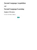
5 It should also be simple in mechanics with an analytical solution available for validation. Three tutorial problems are covered in this Learning Module . Tutorial Problem 1 A long column made of AISI 304 steel has a square cross-section with dimensions of 100mm x 100mm. This column is used to support a 10 MPa pressure load in multiple setups with varying end conditions. Use FEM Analysis to find the Buckling load factor (BLF) and critical pressure load (Pc) of the column in each separate circumstance. The end conditions are as follows: a) One fixed end and one free end (fixed-free) b) Two fixed ends (fixed-fixed) c) One fixed end and one pinned end (fixed-pinned) d) Two pinned ends (pinned-pinned) LM-BK-1 5 Tutorial Problem 2 A m long L-shaped column made of AISI 304 steel has dimensions as shown in the figure below. The column contains sixty 60 mm diameter holes as seen in the figure below. This column is used to support a 6 MPa pressure load in multiple setups with varying end conditions.
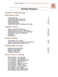
6 Use FEM Analysis to find the Buckling load factor (BLF) and critical pressure load (Pc) of the column in each separate circumstance. The end conditions are as follows: a) One fixed end and one free end (fixed-free) b) Two fixed ends (fixed-fixed) LM-BK-1 6 Tutorial Problem 3 Honeycomb structures are known for their high strength to weight ratios. For simplicity, consider a single honeycomb component with a foil thickness (t) of , a cell size (l) of and a core height (h) of The material used for the manufacturing of the honeycomb structure is Ti-8Al-1Mo-1V Titanium Alloy and the structure is loaded with a 200,000 Mpa pressure load. For this problem, compare the nominal stress and stress/weight ratio of this honeycomb data to a solid block of the same dimensions. Honeycomb Solid Block LM-BK-1 7 5. Conceptual Analysis Conceptual Analysis is the abstraction of the logical steps in performing a task or solving a problem.
7 Conceptual Analysis for FEM simulation is problem type dependent but software-independent, and is fundamental in understanding and solving the problem. Conceptual Analysis for Buckling Analysis reveals the following general logical steps: 1. Pre-processing o Geometry creation o Material property assignment o Boundary condition specification o Mesh generation 2. Solution 3. Post-processing 4. Validation Attachment II discusses the conceptual Analysis for the tutorial problem in this Module . Link to Conceptual Analysis LM-BK-1 8 6. Abstract Modeling Abstract modeling is a process pioneered by CometSolutions Inc. Abstract modeling enables all attributes of an FEM model (such as material properties, constraints, loads, mesh, etc.) to be defined independently in an abstract fashion, thus reducing model complexity without affecting model accuracy with respect to the simulation objective. It detaches attributes from one another, and emphasizes conceptual understanding rather than focusing on software specifics.
8 Evidently, abstract modeling is independent of the specific software being used. This is a fundamental departure from the way most FEM packages operate. Conceptual Analysis focuses on the abstraction of steps necessary for an FEM simulation, while abstract modeling focuses on the abstraction and modularization of attributes that constitute an FEM model. They are powerful enabling instruments in FEM teaching and Learning . Link to Abstract Modeling 7. Software-Specific FEM Tutorials In software-specific FEM tutorial section, the tutorial problem is solved step by step in a particular software package. This section fills in the details of the conceptual Analysis as outlined in previous section. It provides step by step details that correspond to the pre-processing, solution, post-processing and validation phases using a particular software package. Two commercial FEM packages are covered in this Module : SolidWorks and CometSolution.
9 Below are the two links: Link to SolidWorks FEM Tutorial 1 Link to SolidWorks FEM Tutorial 2 Link to SolidWorks FEM Tutorial 3 Link to CometSolution FEM Tutorials 8. Post-Test The post-test will be taken upon completion of the Module . The first part of the post-test is from the pre-test to test knowledge gained by the user, and the second part is focused on the FEM simulation process covered by the tutorial. Link to Post-Test 9. Practice Problems The user should be able to solve practice problems after completing this Module . The practice problems provide a good reinforcement of the knowledge and skills learned in the Module , and LM-BK-1 9 can be assigned as homework problems in teaching or self study problems to enhance Learning . These problems are similar to the tutorial problems worked in the Module , but they involve different geometries and thermal boundary conditions. Link to Practice Problems Link to Solutions for Practice Problems 10.
10 Assessment The assessment is provided as a way to receive feedback about the Module . The user evaluates several categories of the Learning experience, including interactive Learning , the Module format, its effectiveness and efficiency, the appropriateness of the sections, and the overall Learning experience. There is also the opportunity to give suggestions or comments about the Module . Link to Assessment LM-BK-1 10 Attachment A. Pre-Test 1. The internal force per unit area acting inside a body when forces are applied to the body is called: O Stress O Strain O Displacement O Reaction 2. A column will remain stable as long as the applied load does not exceed the: O Maximum load O Critical load O Weight of the column O Minimum load 3. The engineering principle commonly used for column Analysis is: O Bernoulli s Equation O Fourier s Law O Newton s Law O Euler s Formula 4. The slenderness ratio of a column is defined as the column s: O Width divided by the length O Length divided by the radius of gyration O Area divided by the volume O Weight divided by the volume 5.