Transcription of LECTURE 18 Switches and Switch Stress: The …
1 1 LECTURE 18 Switches and Switch Stress: The Concept of SafeOperating Area for a DeviceI. Ideal Switch +V with IOFF +I with VON switching delay and its loss due to Switches : zero in every Loss: RON = 0, VON = Loss: No delays, no devicestored stray Lp or Cp for undesired ringing!F. Real quadrants of operation for realsolid state quadrant and device Switch Stress (S) and SwitchUtilization (U) DefinitionsS(active) ~ V(swoff) rmsI(swon) per switchU P(load)S per of Flyback Converter2V(off) ~ Vg/D }Dopt } forI(on) ~ I D } of Umax and Dopt for various ConvertersThe above selection of solid state Switches will bematched to the I(D) through the device and the V(D)across the device as determined by detailed circuitanalysis in the next few lectures.
2 Analysis of V(D)and I(D) will follow the same procedure as M(D).3 LECTURE 18 Switches and Switch Stress: The Concept of SafeOperating Area for a Switch Characteristics:There are five characteristics of a SPST idealswitch. You make think of a semiconductor powerswitch as you do of a light Switch at home. Itoperates with no concern for losses in either the onor the off + +V with it = 0: No leakage current flows when (ON) 0 at all it, either +i flow on/off or off/on transitions occur with zero delayor instantaneous response time.
3 Therefore, even forfinite V and I during the switching, the energy E =(VI)( t) required to Switch is near zero because theswitch time is assumed to be zero. Removing thisassumption is the first step to understanding realswitches that operate at fSW. Even if the switchtransitions lose only a little energy and with a fast switchtime, they Switch at 100kHz to 1 MHz so that over onesecond close to a million transitions occur, each addingto the total lost required to drive the Switch is negligible. No DC4losses nor any dynamic switching loss.
4 Typically, a Switch drivercontrols 100-1000 times the power it dissipates. However, forsome devices this drive power can approach 10 % of the energyswitched as we will device capacitance is charged or discharged duringVOFF or VON states. No charge Q is stored in semiconductordevices. No inductor current i storage occurs during the on statedue to either real inductors or due to leakage inductance s ofcores or due to wiring. Hence no additional stored energy flows tostress the Switch via either Imax and Vmax. Removing thisassumption is the another big step to truly understanding switchlossesIn summary an ideal Switch is able to pass currents bi-directionallyor to block voltages that SPDT Switches may bemodeled by twosynchronized orcommutatedSPST Switches .
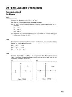
5 One is on whiletwo is off andvice ++--vAvBiAiBiLVgThe ideal Switch model now needs to be deconstructedassumption by assumption to better appreciate Switch losses, which account for 5-15 % of total loss depending on the specificconditions of the PWM converter Real SwitchesThere are five types of real Switches we will predominantly dealwith in power electronics, diodes, bipolar junction transistors(BJT),gate turn-off thyristors(GTO), field effect transistors(FET), andinsulated gate bipolar transistors(IGBT), each of which has uniqueV-I characteristics shown types of Real Switches Switch Property 1.
6 Passes current in one direction, blocks in the other1. Diode2. Passes or blocks current in one direction2. BJT3. Can pass in one direction or block in both directions3. GTO4. Can pass in both directions, but blocks in only one direction4. FET5. Passes or blocks current in one direction 5. IGBT 1. Diode2. BJT3. GTO4. FET5. IGBTD eviceSymbol(including body diode)We need to realize that each Switch has unique and limitedturn-on and turn-off characteristics. Hence, depending on what isrequired in terms of current passing through the device when it ison and voltage that the device is required to block when it is off,we may have only one choice for a Switch regardless of cost.
7 Ofcourse some circuit circumstances allow for us to choose fromseveral Switch possibilities, perhaps introducing cost as a final6determining factor. Below we examine the diode and transistorswitches briefly in a four quadrant V-I space to introduce theconcept of safe operating area (SOA) for the specific Switch . This is a rule of thumb that is easy to define and provided by eachswitch manufacturer to guide the user. For any realsemiconductor Switch as opposed to mechanical Switches multi-quadrant operation is never easy unless we employ series andparallel combinations of our five main quadrant operation is notpossible in single device solidstate Switches .
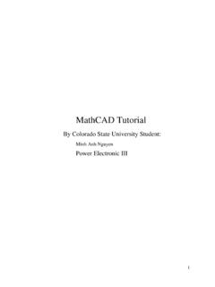
8 To achieve fourquadrants one needs severaldevices in variousseries/parallel quadrant switchesviAswitch Aonvswitch BoniBiLiLVg-Vgswitch Boffswitch AoffSW A is?Pnpbipolar?MOSFET?SW B is?Diode,other?Note the difference between bipolar transistors (only one-waycurrent flow) and MOSFETs, (bi-directional current flow). Also, thebipolar of a different type can indeed stand off the oppositepolarity but current flow is one-way, the other way. The key toconsider in one quadrant Switches is the Vmax(off) and Imax(on)levels the Switches are subjected to by circuit +-vBVgiL(t)L+-vAiAiBTo help thinking, considerthe specific example ofboth Switches above in abuck simple one quadrant Switches are as shown below forboth switchesSW Aa)CC10i+i-v10+-vvionoffstands offVgb)BJT and IGBT symbols (a), andtheir idealized switchcharacteristics (b).
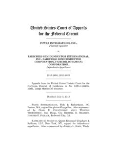
9 SW B10+-vivionoffstands offVoutDiode symbol and its dynamic behavior during switching from a static off/on state tothe other static state depends both on the Switch device and thecircuit. In the figure below we show three curves:1. Perfect Switch trajectories2. Typical turn-on V-I trajectory3. Typical turn-off V-I trajectory8 Switch current vs. voltage, showing the switching safe operating area as obtained from the manufacturersdevice specifications must lie well outside switching trajectories asshown below:Switching trajectories within safe operating manufacturers also provide estimated device switchingtimes based on operating conditions to better estimate the energylost during switching W = V*I dt.
10 First lets refresh our memory on bipolar diode and transistor DCcharacteristics as well as some dynamic issues for these two onequadrant Switches . Hopefully, this is a review for most students. Ifnot we will cover these devices again when we focus in on thepower electronic versions of these classic devices . All bets are offthat these power electronic versions even vaguely resemble themicroelectronic versions, especially for FET s9 Static models of diodes involve the following:RoffRonVonFor HW #4 from the MUR3040PT diode data book forpractice obtain all three values: Ron = , Roff = 40 m , andVon = characteristics do not tell the full story of any device.