Transcription of Lecture 2. Power semiconductor devices (Power switches)
1 Power Electronics Lecture Tawfeeq Alzuhairi 1 Lecture 2. Power semiconductor devices ( Power switches) Power semiconductor switches are the work-horses of Power electronics (PE). There are several Power semiconductors devices currently involved in several industrial applications. PE switches works in two states only: Fully on (conducting, and Fully off (blocking) . Switches are very important and crucial components in Power electronic systems What is a good Power switch: No Power loss when ON No Power loss when OFF No Power loss during turning ON or OFF Little Power required to turn it ON or OFF Bi- directional? Adequate voltage and current ratings Low Turn-on and Turn-off times Basic ratings: carrying current, blocking voltage.)
2 Speed. Any real device requires a definite time to switch. Second-order ratings: di/dt, dv/dt, momentary capabilities. Power loss Thermal ratings from Power switching devices to heat sink Control ratings: how to operate the switch TYPES OF Power semiconductor SWITCHES The main types of Power semiconductor switches in common use are 1. Power Diodes 2. Thyristor devices a. silicon controlled rectifier (SCR) b. Static induction thyristor (SITH) c. Triac (Triode ac switch) Power Electronics Lecture Tawfeeq Alzuhairi 2 d. Gate turn-off thyristor (GTO) e. Mos- controlled thyristor (MCT) f. integrated gated-commutated thyristor (IGCTs) 3. Power transistors a. Bipolar junction transistor (BJT) b. Metal oxide semiconductor field effect transistor (MOSFET) c.
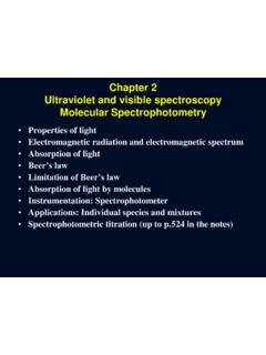
3 Insulated gate bipolar transistor (IGBT) d. Static induction transistor (SIT) Power Diodes: These are two terminal switches, as shown in Fig. -a, formed of a pn junction. It is not controllable and its operating states are determined by the circuit operating point. When diode is forward biased, it conducts current, a forward positive voltage Vo will turn it on. When it reversed biased (a reverse negative current from Cathode to Anode) will turn it off. With forward biasing a small forward voltage (VF) will appear across it ( ). Practically, the diode characteristic consists of two regions, as shown in Fig. -b; a forward bias region (ON state) where both vD and iD are positive and the current in this region increases exponentially with the increase in the voltage, and a reversed bias region (OFF state) where both vD and iD, are negative and very small leakage current ( A to mA) flows through the diode until the applied reverse voltage reaches the diode s breakdown voltage limit VBR.
4 Ideally, the diode is represented by a short circuit when forward biased and as an open circuit when reversed biased with the ideal characteristic shown in Fig. Diode: a) symbol, b) characteristic, and c) ideal characteristic . Power Electronics Lecture Tawfeeq Alzuhairi 3 Types of Power Diodes: ( : Line frequency (general purpose 1. on state voltage very low (below 1 V) large reverse recovery time trr (about 25 s) . very high current (up to 6 kA) and voltage (8 kV) ratings used in line-frequency (50/60Hz) applications such as rectifiers. Slow recovery ( ) trr =reverse recovery time 2. Fast recovery: very low trr (<1 s). Power levels at several hundred volts and several hundred amps.
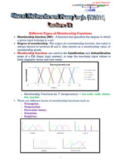
5 Normally used in high frequency circuits. 3. Schottky : very low forward voltage drop (typical ) limited blocking voltage (50-100V) . used in low voltage, high current application such as switched mode Power supplies. Thyristors ( silicon Controlled Rectifiers SCRs ) The thyristor ,it is also called silicon controlled rectifier (SCR), is a four-layer, three terminal switching semiconductor device, with each layer consisting of an alternately N or P-type material, for example N-P-N-P. The main terminals, labeled anode and cathode, are across the full four layers, and the control Power Electronics Lecture Tawfeeq Alzuhairi 4 terminal, called the gate, is attached to one of the middle layers as shown in Symbol 2-Transistor Analogy : The thyristor and its equivalent 2-transistor circuit.
6 SCRs are mainly used where high currents and voltages are involved, and are often used to control alternating currents, where the change of sign of the current causes the device to automatically switch off. Like a diode, an SCR conducts only in one SCR symbol and its ideal characteristic are shown in Fig, Modern SCRs can switch large amounts of Power (up to megawatts). In the realm of very high Power applications, they are still the primary choice. SCR is a controllable switch that usually required to be latched to conduct. This latching (triggering) process is carried out by injecting current to the gate terminal (ig), , at the required latching instant provided that the device is forward biased (vAK is positive). Practically, the thyristor characteristic has three main regions as shown in Fig.
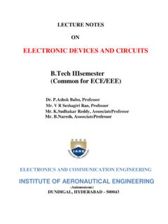
7 ; the Conduction Region where the thyristor is operating in its ON state, the Forward Blocking Region where the thyristor is forward biased but not yet triggered or the voltage didn t reach the forward breakover voltage, and the Reverse Region that consists of the reverse blocking region and the reverse avalanche region similar to the diode characteristic. Power Electronics Lecture Tawfeeq Alzuhairi 5 Fig. Thyristor:( a) symbol, (b) ideal characteristic , Thyristor gate circuit Fig. Thyristor (SCR) characteristic Power Electronics Lecture Tawfeeq Alzuhairi 6 Thyristors can only be turned on with three conditions: 1.
8 The device must be forward biased, , the anode should be more positive than the cathode. 2. A positive gate current (Ig) should be applied at the gate. 3. the current through the thyristor should be more than the latching current. Once conducting ,the anode current is LATCHED (continuously flowing). Important points for the SCR characteristic: o Latching Current: This is the minimum current required to turn on the SCR device and convert it from the Forward Blocking State to the ON State. o Holding Current: This is the minimum forward current flowing through the thyristor in the absence of the gate triggering pulse. o Forward Breakover Voltage: This is the forward voltage required to be applied across the thyristor to turn it ON without the gate signal application. o Max Reverse Voltage: This is the maximum reverse voltage to be applied across the thyristor before the reverse avalanche occurs.
9 Ideally, SCRs are represented by a short circuit when operating within the conduction region and as an open circuit when operating within the blocking region. The ideal characteristic is shown in Fig. 2-b. It is also worth mentioning that once the SCR is triggered and turned ON the gate signal can be removed without turning it OFF. SCRs are turned OFF when reversing the terminal voltage and current. Turning on/off mechanism Thyristor (SCR) Conduction In reverse -biased mode, the SCR behaves like a diode. It conducts a small leakage current which is almost dependent of the voltage, but increases with temperature. When the peak reverse voltage is exceeded, avalanche breakdown occurs, and the large current will flow. In the forward biased mode, with no gate current present ( in the untriggered state, the device exhibits a leakage current.)
10 If the forward breakover voltage (Vbo) is exceeded, the SCR self-triggers into the conducting state and the voltage collapses to the normal forward volt-drop, typically The presence of any gate current ig will reduce the forward breakover voltage and will trigger the thyristor at any required instant ( ), see Power Electronics Lecture Tawfeeq Alzuhairi 7 Thyristor turn off The process of turning OFF SCR is defined as "Commutation". Thyristor cannot be turned off by applying negative gate current. It can only be turned off if the current I through it goes negative (reverse). In all commutation techniques, a reverse voltage is applied across the thyristor during the turn OFF process. There are two methods by which a thyristor can be turned OFF.