Transcription of LECTURE NOTES
1 IARE AC Machines Page | 1 LECTURE NOTES ON AC MACHINES 2018 2019 II B. Tech II Semester (IARE-R16) Mr. K Devender Reddy, Assistant Professor Department of Electrical and Electronics Engineering INSTITUTE OF AERONAUTICAL ENGINEERING (Autonomous) Dundigal, Hyderabad - 500 043 IARE AC Machines Page | 2 UNIT-I Three Phase Induction Motor Introduction The induction machine was invented by NIKOLA TESLA in 1888. Right from its inception its ease of manufacture and its robustness have made it a very strong candidate for electromechanical energy conversion.
2 It is available from fractional horsepower ratings to megawatt levels. It finds very wide usage in all various application areas. The induction machine is an AC electromechanical energy conversion device. The machine interfaces with the external world through two connections (ports) one mechanical and one electrical. The mechanical port is in the form of a rotating shaft and the electrical port is in the form of terminals where AC supply is connected. There are machines available to operate from three phase or single phase electrical input. In this module we will be discussing the three phase induction machine. Single phase machines are restricted to small power levels.
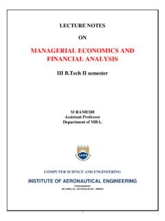
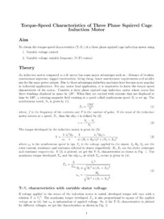
3 Construction In actual practice, the three coils form three windings distributed over several slots. These windings may be connected in star or delta and three terminations are brought out. These are conventional three phase windings which are discussed in greater detail in the chapters on alternators. Such windings are present n the stator as well as rotor Figure 1: stator of an induction machine A photograph of the stator of an induction machine is shown in fig. 1. A close up of the windings is shown in fig. several turns that makeup a coil are seen in this picture. The three terminations are connected to rings on which three brushes make a sliding contact. As the rotor rotates the brushes slip over the rings and provide means of connecting stationary external circuit elements to the rotating windings.
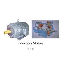
4 A schematic of these arrangements is shown in fig. 8. A photograph of a wound rotor for an induction machine is shown in fig. 3 Fig. 4 shows a close up of the slip ring portion. Brushes are not shown in this picture. Induction machines, which have these kinds of windings and terminals that are brought out, are called slip ring machines. The reader may note that in order that torque is produced current must flow in the rotor. To achieve that, the stationary brush terminals must either be shorted, or connected to a circuit allowing current flow. IARE AC Machines Page | 3 Sometimes a star connected resistor bank is connected so that the developed starting torque is higher.
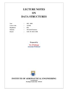
5 There are also other forms of power electronic circuitry that may be connected to the rotor terminals to achieve various functions. The popularity of the induction machine however, stems from another variety of rotor Figure2: Coils in the stator Figure 3: A wound rotor with slip rings IARE AC Machines Page | 4 Figure 4: slip rings Slip rings(fixed to shaft) Rotor shaft Winding v Brushes(stationary) on rotor Sliding Contact Stationary terminals Figure 5: Slip rings and brushes in induction machines a schematic That is used. This rotor has slots into which copper or aluminum bars are inserted.
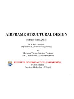
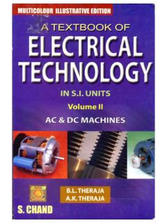
6 These bars are then shorted by rings that are brazed on to each of the rotor ends. Figure 9 shows a simple schematic. Figure 6: squirrel cage rotor a schematic Such a rotor is called squirrel cage rotor. This rotor behaves like a short-circuited winding and hence the machine is able to perform electromechanical energy conversion. This type of rotor is easy to manufacture, has no sliding contacts and is very robust. It is this feature that makes induction machine suitable for use even in hazardous environments and reliable operation is achieved. The disadvantage of this type of rotor is that the motor behavior cannot be altered by connecting anything to the rotor there are no rotor terminals. Fig. 7 shows a photograph of a squirrel cage rotor.
7 The rotor also has a fan attached to it. This is for cooling purposes. The bars (white lines on the surface) are embedded in the rotor iron which forms the magnetic circuit. IARE AC Machines Page | 5 The white lines correspond to the visible portion of the rotor bar. Sometimes two rotor bars are used per slot to achieve some degree of variability in the starting and running performances. It is to make use of the fact that while high rotor Figure 7: squirrel cage rotor Resistance is desirable from the point of view of starting torque; low rotor resistance is desirable from efficiency considerations while the machine is running.
8 Such rotors are called double cage rotors or deep-bar rotors . To summarize the salient features discussed so far, 1. The stator of the 3 - phase induction machine consists of normal distributed AC windings. 2. Balanced three phase voltages impressed on the stator, cause balanced three phase currents to flow in the stator. 3. These stator currents cause a rotating flux pattern (the pattern is a flux distribution which is sinusoidal with respect to the space angle) in the air gap. 4. The rotating flux pattern causes three phase induced EMFs in rotor windings (again normal ac windings). These windings, if shorted, carry three phase-balanced currents. Torque is produced as a result of interaction of the currents and the air gap flux.
9 5. The rotor may also take the form of a squirrel cage arrangement, which behaves in a manner similar to the short-circuited three phase windings. IARE AC Machines Page | 6 The Rotating Magnetic Field The principle of operation of the induction machine is based on the generation of a rotating magnetic field. Let us understand this idea better. Click on the following steps in sequence to get a graphical picture. It is suggested that the reader read the text before clicking the link. Consider a cosine wave from 0 to 360 . This sine wave is plotted with unit amplitude. Now allow the amplitude of the sine wave to vary with respect to time in a sinusoidal fashion with a frequency of the maximum value of the amplitude is, say, 10 units.
10 This waveform is a pulsating sine wave. iapk = Im cos 2 . (1) Now consider a second sine wave, which is displaced by 120 from the first And allow its amplitude to vary in a similar manner, but with a 120 time lag. ibpk = Im cos(2 . 120 ) (2) Similarly consider a third sine wave, which is at 240 lag.. And allow its amplitude to change as well with a 240 time lag. Now we have three pulsating sine waves. icpk = Im cos(2 . 240 (3) Let us see what happens if we sum up the values of these three sine waves at every angle. The result really speaks about Tesla s genius. What we get is a constant amplitude travelling sine wave! In a three phase induction machine, there are three sets of windings phase A winding, phase B and phase C windings.)


![Wind Farm Electrical Systems.pptx [Read-Only]](/cache/preview/8/3/4/a/7/7/3/b/thumb-834a773be91d444a92c541b6bc1b2269.jpg)