Transcription of Lecture Notes for Digital Electronics - University of Oregon
1 Lecture Notes for Digital ElectronicsRaymond E. FreyPhysics DepartmentUniversity of OregonEugene, OR 97403, 20001 Basic Digital ConceptsBy converting continuous analog signals into a nite number of discrete states, a processcalleddigitization, then to the extent that the states are su ciently well separated so thatnoise does create errors, the resulting Digital signals allow the following (slightly idealized): storage over arbitrary periods of time flawless retrieval and reproduction of the stored information flawless transmission of the informationSome information is intrinsically Digital , so it is natural to process and manipulate itusing purely Digital techniques. Examples are numbers and drawback to digitization is that a single analog signal ( voltage which is afunction of time, like a stereo signal) needs many discrete states, orbits, in order to givea satisfactory reproduction.
2 For example, it requires a minimum of 10 bits to determine avoltage at any given time to an accuracy of 0:1%. For transmission, one now requires 10lines instead of the one original analog explosion in Digital techniques and technology has been made possible by the incred-ible increase in the density of Digital circuitry, its robust performance, its relatively low cost,and its speed. The requirement of using many bits in reproduction is no longer an issue:The more the circuitry is based upon the transistor, which can be operated as a switch withtwo states. Hence, the Digital information is intrinsicallybinary. So in practice, the termsdigital and binary are used interchangeably.
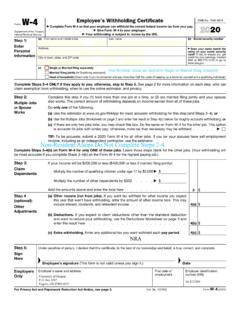
3 In the following sections we summarize someconventions for de ning the binary states and for doing binary Logic StatesThe following table attempts to make correspondences between conventions for de ningbinary logic states. In the case of the TTL logic gates we will be using in the lab, theLowvoltage state is roughly 0{1 Volt and theHighstate is roughly 2:5{5 Volts. See page 475 ofthe text for the exact conventions for TTL as well as other hardware gate LogicBoolean AlgebraVoltage StateVoltage State(positive true)(negative true )True (T)1 High (H)Low (L)False (F)0 LHThe convention for naming these states is illustrated in Fig. 1. The \positive true" caseis illustrated. The relationship between the logic state and label (in this case \switch open")at some point in the circuit can be summarized with the following:The labelled voltage isHigh (Low)when the label's stated function isTrue (False).}}
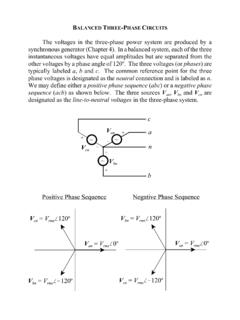
4 In the gure, the stated function is certainly true (switch open), and this does correspond toa high voltage at the labelled point. (Recall that with the switch open, Ohm's Law impliesthat with zero current, the voltage di erence across the \pull up" resistor is zero, so that1the labelled point is at +5 Volts. With a closed switch, the labelled point is connected toground, with a 5 Volt drop across the resistor and a current ofI=V=R= 5 mA throughit.)+5 V1 kswitch openFigure 1: Illustration for labelling logic states (\positive true").With the convention known as \negative true", the label would be changed to \switchclosed" with a bar over it:switch closed. Our statement becomes:The labelled voltage isLow (High)when the label's stated function isTrue (False).
5 So in the gure, the stated function (switch closed) is true when the voltage is low. The baris meant to envoke the boolean inversion operation: T=F, F=T, T=T, and so ArithmeticEach digit in binary is a 0 or a 1 and is called abit, which is an abbreviation ofbinary are several common conventions for representation of numbers in most familiar isunsigned binary. An example of a 8-bit number in this case is010011112=0 27+1 26+ +1 20=64+8+4+2+1=7910(Generally the subscripts will be omitted, since it will be clear from the context.) To convertfrom base 10 to binary, one can use a decomposition like above, or use the following algorithmillustrated by 79: 79=2 = 39, remainder 1, then 39=2 = 19 r 1, and so forth.
6 Then assembleall the remainders in reverse largest number which can be represented bynbits is 2n 1. For example, with 4bits the largest number is 11112= most signi cant bit (MSB) is the bit representing the highest power of 2, and theLSB represents the lowest power of with unsigned binary is analogous to decimal. For example 1-bit additionand multiplication are as follows: 0 + 0 = 0, 0 + 1 = 1, 1 + 1 = 0, 0 0=0,0 1 = 0, and1 1 = 1. Note that this isdi erent from Boolean algebra,asweshallseeshortly,where1+1= convention is calledBCD(\binary coded decmal"). In this case each decimaldigit is separately converted to binary. Therefore, since 7 = 01112and 9 = 10012,then79 = 01111001 (BCD).
7 Note that this isdi erentthan our previous result. We will useBCD quite often in this course. It is quite convenient, for example, when decimal numericaldisplays are another convention isGray code. You have a homework problem to practice is less commonly of Negative NumbersThere are two commonly used conventions for representing negative magnitude, the MSB is used to flag a negative number. So for example with4-bit numbers we would have 0011 = 3 and 1011 = 3. This is simple to see, but is notgood for doing 's complement, negative numbers are designed so that the sum of a number andits 2's complement is zero. using the 4-bit example again, we have 0101 = 5 and its 2'scomplement 5 = 1011.
8 Adding (remember to carry) gives 10000 = 0. (The 5th bit doesn'tcount!) Both addition and multiplication work as you would expect using 2's are two methods for forming the 2's complement:1. Make the transformation 0!1and1!0, then add Add some number to 2 MSBto get the number you want. For 4-bit numbers anexample of nding the 2's complement of 5 is 5= 8 + 3 = 1000 + 0011 = RepresentationIt is very often quite useful to represent blocks of 4 bits by a single digit. Thus in base16 there is a convention for using one digit for the numbers 0,1,2,:::,15 which is calledhexadecimal. It follows decimal for 0{9, then uses letters A{ Logic Gates and Combinational Types and Truth TablesThe basic logic gates areAND, OR, NAND, NOR, XOR, INV,andBUF.}}
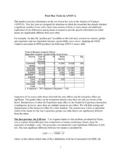
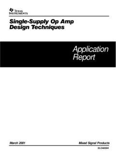
9 The last two are notstandard terms; they stand for \inverter" and \bu er", respectively. The symbols for thesegates and their corresponding Boolean expressions are given in Table of the text which,for convenience, is reproduced (in part) in Fig. 2: Table from the of the logical gate functions, as well as the Boolean relations discussed in the nextsection, follow from the truth tables for theANDandORgates. We reproduce these also show theXORtruth table, because it comes up quite often, although, as we shall see,it is not BQABQ000100010111 Figure 3 4 5:XOR(exclusiveOR) Algebra and DeMorgan's TheoremsBoolean algebra can be used to formalize the combinations of binary logic states.
10 Thefundamental relations are given in Table of the text. In these relations,AandBarebinary quantities, that is, they can be either logical true (Tor 1) or logical false (For 0).Most of these relations are obvious. Here are a few of them:AA=A;A+A=A;A+A=1;AA=0;A=ARecall that the text sometimes uses an apostrophe for inversion (A0). We use the standardoverbar notation (A).We can use algebraic expressions to complete our de nitions of the basic logic gateswe began above. Note that the Boolean operations of \multiplication" and \addition" arede ned by the truth tables for theANDandORgates given above in Figs. 3 and 4. Usingthese de nitions, we can de ne all of the logic gates algebraically.