Transcription of LED MOTION ACTIVATED FLOOD LIGHT - Good Earth Lighting
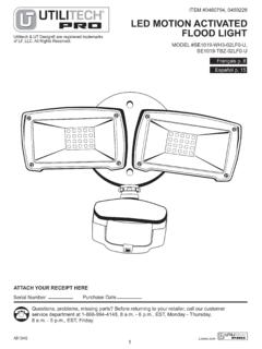
1 LED MOTION ACTIVATED FLOOD LIGHTITEM #0611551, #0611550 MODEL #SE1036-BP2-02LF0-U, SE1036-WH3-02LF0-UUtilitech & UT Design are registered trademarks of LF, LLC. All Rights Reserved. Fran ais p. 10 Espa ol p. 19 Serial NumberPurchase DateQuestions, problems, missing parts? Before returning to your retailer, call our customer service department at 1-866-994-4148, 8 - 6 , EST, Monday - Thursday, 8 - 5 , EST, YOUR RECEIPT : Hardware shown actual 2 BBMounting Strap(Not shown to size)Qty. 1 CCWire NutQty. 3 DDEEFFSAFETY INFORMATIONP lease read and understand this entire manual before attempting to assemble, operate or install the product.
2 SAVE THESE INSTRUCTIONS IN A LOCATION CLOSE TO YOUR LIGHT FIXTURE SO YOU CAN REFER TO THEM AT A LATER TIME. the new one. LED electronics can be damaged by electrostatic discharge (ESD) shock. Before installation, discharge yourself by touching a grounded bare metal surface to remove this hazard. To avoid damage, do not remove the clear lens over the LED module. DO NOT USE THIS FIXTURE WITH A DIMMING CIRCUIT. If you currently have dimmer controls, you will need to remove them and replace them with regular electrical switches. If you have a three-way dimmer, you will have to replace it with a regular three-way switch.
3 If you are unfamiliar with electrical WARNINGCAUTIONPACKAGE CONTENTSHARDWARE CONTENTS P ARTS DESCRIPTION QUANTITY A LED Head 2 B Sensor Arm 1 P ARTS DESCRIPTION QUANTITY C Sensor Head 1 D Wall Plate 2 LongMachineScrewQty. 1 SilconeCapQty. 1 Foam Gasket(Not shown to size)Qty. INFORMATIONIMPORTANT SAFETY INSTRUCTIONS 1. Turn power OFF before installing or servicing. 3. Do NOT remove the protective LED lens. 4. Do NOT look directly at lighted LEDs for any length of time. 5. Do NOT leave bare wires exposed outside the wall canopy enclosure.
4 6. Electrical requirements: 120 V AC, 60 Hz., Minimum 90 supply conductors. 7. Suitable for wall or eave mounting onto recessed or round surface mounted electrical boxes rated for wet locations. Not suitable for ground mount electrical boxes. 8. Do NOT allow the sensor head to touch the LED head housing. Maintain at least 1 in. spacing between the LED heads and the sensor head. 9. For proper operation and protection against water damage, the MOTION sensor adjustment controls MUST be facing Do NOT mount below 5 Do not mount near other LIGHT sources that can compromise the dusk to dawn This device complies with Part 15 of the FCC rules.
5 Operation is subject to the following two conditions: (1) This device may not cause harmful interference, and (2) this device must accept any interference received, including interference that may cause undesired beginning installation of product, make sure all parts are present. Compare parts with package contents list and hardware contents list. If any part is missing or damaged, do not attempt to install the product. Estimated Assembly Time: 45 minutes. Tools Required for Assembly (not included): Phillips screwdriver and silicone adhesive or bodies of water, or trees/bushes that move in the wind.
6 All of these may trigger the MOTION sensor security LIGHT and may be disruptive to the intended operation of the LIGHT . Do NOT install near other sources of LIGHT . The other LIGHT sources can fool the dusk to dawn sensor into thinking it is box that has more than two wire leads, mark the wires to keep track of the correct ones to use. 1. Pull the supply wires out of the electrical box. Using box, secure the mounting strap (CC) to the electrical box, making sure that the side marked FRONT is facing INSTRUCTIONS FOR ROUND SURFACE MOUNT ELECTRICAL BOXES1 GNDFRONTCCAAH ardware UsedMachine Screwsx 2 AABBM ounting Strapx 1 CCGNDFRONTINSTALLATION INSTRUCTIONS FOR ROUND SURFACE MOUNT ELECTRICAL BOXES2.
7 Remove the protective paper barrier from the adhesive face of the foam gasket (GG). Trace the supply wires through the openings in the gasket and adhere the gasket to the mounting strap and outer edge of the round surface mount electrical Position the wall plate over the mounting strap so the center hole of the wall plate aligns with the center hole in the mounting strap. While holding the wall plate in place, put the long machine screw (EE) through the center hole of the wall plate and mounting strap. Tighten the screw properly to secure the wall plate onto the electrical box. NOTE: Make sure the gasket (GG) properly seals the gap between the wall plate and the electrical box to prevent water seepage into the electrical box.
8 Hardware Screwx 1EE4 Hardware UsedWire Nutx 3 DDproperly grounded. If unfamiliar with the methods of properly electrical box is made of plastic and/or has a green or bare the electrical box ground wire should be connected together using one of the small wire nuts (included). If the electrical box is made of metal and already grounded, secure the bare GND using the green grounding screw. Connect the is connected to the white supply lead. Tighten the wire nuts properly to prevent them from coming loose. If needed, use electrical tape to secure the wire nuts onto the wire leads. Push the excess wires back into the electrical with the adjustment controls and drain holes facing downward to prevent water damage.
9 The position of the sensor head should not exceed 45 degrees from Used3 GNDFRONTGNDFRONTDDDD2 GNDFRONTGGFoam Gasketx 1GG4EE45 45 45 45 556. Restore power to the electrical box at the circuit breaker or fuse panel. Make sure the wall switch that controls the electrical box for your security LIGHT is returned to the ON position and check that your LIGHT is functioning properly. (FF) into the mounting screw opening to prevent water seepage into the INSTRUCTIONS FOR RECESSED ELECTRICAL BOXES electrical box that has more than two wire leads, mark the wires to keep track of the correct ones to use. 1. Pull the supply wires out of the electrical box.
10 Using box, secure the mounting strap (CC) to the electrical box, making sure that the side marked FRONT is facing properly grounded. If unfamiliar with the methods of electrician. A green copper ground wire is pre-attached or has a green or bare copper grounding wire inside, the should be connected together using one of the small wire nuts (included). If the electrical box is made of metal ground wire to the mounting strap marked GND using the green grounding screw. Connect the supply leads from the to the white supply lead. Tighten the wire nuts properly to prevent them from coming loose. If needed, use electrical tape to secure the wire nuts onto the wire leads.