Transcription of Leroy-Somer D510C Spannungsregler - Handbuch - …
1 D 510C X2 Z1 X1 Z2F+ F-L1 L2 U V WW V U+10V -A|1 -A|2 -0V -A01 -0V -D|1 -D|2 -0V -D01 = UPowerUSB+ -D510 CDigital voltage regulatorInstallation and / pElectric Power Generation2 Installation and maintenanceD510 CDigital voltage regulator4243 en -SAFETY MEASURESB efore using your machine for the first time, it is important to read the whole of this installation and maintenance necessary operations and interventions on this machine must be performed by a qualified technical support service will be pleased to provide any additional information you may various operations described in this manual are accompanied by recommenda-tions or symbols to alert the user to potential risks of accidents.
2 It is vital that you under-stand and take notice of the following war-ning symbol for an operation capable of damaging or destroying the machine or surrounding equipment. Warning symbol for general danger to personnel. Warning symbol for electrical danger to servicing or repair operations perfor-med on the AVR should be undertaken by personnel trained in the commissioning, servicing and maintenance of electrical and mechanical components. When the generator is driven at a frequency below 28 Hz for more than 30 seconds with an analogue AVR, its AC power supply must be disconnected. WARNINGThis AVR can be incorporated in a EC-marked manual is to be given to the end user.
3 - We reserve the right to modify the characteristics of this product at any time in order to incorporate the latest technological developments. The information contained in this document may therefore be changed without document may not be reproduced in any form without prior brands and models have been registered and patents applied manual concerns the alternator AVR which you have just wish to draw your attention to the contents of this maintenance / pElectric Power Generation3 Installation and maintenanceD510 CDigital voltage regulator4243 en -CONTENTS1 - PRESENTATION .. - Operation .. - Characteristics .. - Specifications ..92 - HUMAN-MACHINE INTERFACE .. - Communication.
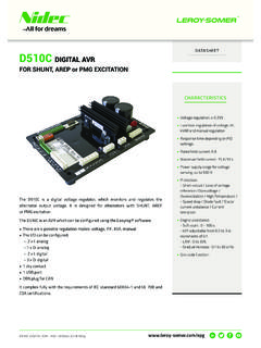
4 - Analog I/O .. - Digital I/O .. - The LEDs .. - Wiring scheme ..123 - SETTING THE FUNCTION PARAMETERS .. - Installation .. - Startup .. - Appearance .. - Configuration in customised mode .. - Advanced Grid code - Dead bus synchronization ..464 - CONNECTION DIAGRAMS ..485 - DIMENSIONS AND MOUNTING .. - Top view .. - Side view ..496 - FAULT FLOW CHARTS ..507 - SPARE PARTS .. - Designation .. - Technical support service ..60 Disposal and recycling instructionsThe temperature can more than 70 C in surface, the product must be place inside the terminal box or an electrical AVR is IP00, it must be incorporated in an environment which ensures it a IP20 / pElectric Power Generation4 Installation and maintenanceD510 CDigital voltage regulator4243 en -General descriptionThis manual describes how to install, use, set up and maintain the D510 C purpose of this AVR is to regulate alternators with a field current of less than 6 A in continuous operations, and 15 A maximum in the event of short-circuit for 10 seconds is designed for mounting in a generator terminal box or a control cabinet.
5 It must be installed in compliance with local protection and safety standards, especially those specific to electrical installations with a maximum voltage of 300 VAC is an electronic card molded in a polyurethane softwareThe D510C must be configured using the dedicated EasyReg software (only compatible with PCs). The EasyReg software is available on the Leroy-Somer the code or go to access product documentation and / pElectric Power Generation5 Installation and maintenanceD510 CDigital voltage regulator4243 en -1 - - OperationA schematic diagram of the D510C appears below. = = = CPIDDSP trans-ceiver PX1Z1X2Z2B+B-UVWIUIVIWL1L2F+USBF-CAN-HCA N-LPT100/CTPPT100PT100DI1DI2AI 1AI / pElectric Power Generation6 Installation and maintenanceD510 CDigital voltage regulator4243 en -TerminalsSignalsSchemeX1X2Z1Z2 Power supply- Auxiliary winding input- PMG input- SHUNT inputD510CX1 ABb1b2 ABX2Z1Z2L1L2 Mains voltage measurement8M 8M UVWA lternator voltage measurementFor single-phase: use V and W8M 8M 8M 8M CT+15V-15V+15V-15V+15V-15 VAltIU = (s1, s2)IV = (s1, s2)IW = (s1, s2)Alternator current measurementAI1AI2 Analog inputs:External setting4-20mAPOT0-10V500 332 210k +33V0 VDI1DI2 Digital inputs.
6 U=U and PF/kVAR regulationDI1/DI22k21+15V0V10kB+B-DC power supplyB+B-D510C1A or 5 AAI1 or AI2 Mainsup to180 Vup to530V11V / pElectric Power Generation7 Installation and maintenanceD510 CDigital voltage regulator4243 en -TerminalsSignalsSchemeF+F-Field excitation: 6 Aup to 15 A/10 sF+F-ExciterCTPPT100_1PT100_2PT100-3 Temperature sensors 5V4k75PT100- CTP+5V100nFCAN_HCAN_LCAN BUS PCANT ransceiverHLUSB_D+USB_D-USB communication port PUSBC ontrollerD-D++ / pElectric Power Generation8 Installation and maintenanceD510 CDigital voltage regulator4243 en - Power: It varies according to the type of field excitation (3 types).- AREP: The AVR is powered by two auxiliary windings which are independent of the voltage sensing first winding has a voltage in proportion with that of the alternator and the second has a voltage in proportion with the stator PMG: A permanent magnet generator (PMG) added to the alternator supplies the AVR with voltage which is independent of the main alternator SHUNT: The AVR is powered by the main winding (140 V 50/60 Hz).
7 Two fuses 10A/250 VAC, Ref. Mersen: E084414P - MI6SA25V10/50 or equivalent, mounted externally of the D510C must be used in the three types of excitation. Battery: This is used to supply the AVR with between 11 V and 30 V. It must always be battery supply must be protected by a 1 A Ref. Mersen : A217028Q - GDL1 or equivalent fuse. Mains: This input is dedicated to the measure phase-to-phase mains voltage which will be taken as the reference when voltage matching is performed. Alternator voltage: This input measures the alternator output voltage to the AVR in:- three-phase (U, V, W)- single-phase (V, W) Current transformer(s): This input measures the current supplied by the alternator.
8 It must always be present when the alternator is running in parallel operation or at PF or KVAR regulation or stator current limitation. The possible configurations are:- 1 CT on phase U- 3 CTs on phases U, V and W Temperature sensor(s): These are used to measure the alternator temperature and alert the user if there is a rise in temperature. This measurement can be taken either with 1 PTC or 3 PT100s. Communication:- USB port: This is used to connect the AVR to a computer and creates the link between the EasyReg software and the CAN port: This is used to connect the AVR to a bus CAN interpreter in order to exchange parameters with the D510C . I/O: This part is used to:- Enter settings - Send information from the D510C - Receive information from the alternator LEDs: These light-emitting diodes inform the user whether the AVR is working correctly or / pElectric Power Generation9 Installation and maintenanceD510 CDigital voltage regulator4243 en - CharacteristicsThe different functions of the D510C are:- Voltage regulation- Regulation of the power factor (PF)- Regulation of the reactive power- Manual regulation (Iexc) Voltage regulation: The D510C regulates the alternator output voltage.
9 Regulation is applied to the mean value or the true rms value (TRMS). Regulation of the power factor: The D510C regulates the power factor. This is the ratio between the active power (P = 3*U*I*cos ) and the apparent power (S = 3*U*I). - Inductive [0; /2] means that the current is lagging behind the voltage. The load is inductive (induction motor, transformer, etc).- Capacitive [ /2; ] means that the current is leading the voltage. The load is capacitive (fluorescent lighting, etc). Regulation of the reactive power: The D510C regulates the reactive power (Q = 3*U*I*sin ) at a fixed value. Manual regulation: The D510C can regulate the excitation functions are selected when setting the AVR - - CharacteristicsNameMinimum valueMaximum valueAdjustableBattery power supply11 V30 V-Alternator frequency10 Hz100 HzYe sMains frequency10 Hz100 Hz-Single-phase mains voltage50 V530 V-Mains voltage ratio1100Ye sExcitation current0 A6 A-Max.
10 Excitation current 0 A15 A/10s-Single-phase alternator voltage0 V530 V-Three-phase alternator voltage0 V530 V-Alternator current input1 A5 AYe sAlternator I u0 A5000 A-Alternator I v0 A5000 A-Alternator I w0 A5000 / pElectric Power Generation10 Installation and maintenanceD510 CDigital voltage regulator4243 en -NameMinimum valueMaximum valueAdjustableLAM knee-point37 Hz*100 Hz* Ye s*Adjustable LAM70% ofVoltage reference100% ofVoltage referenceYe sVariable sVoltage reference setpoint90 V530 V**Ye sAdjustment of external accuracy- 10%** + 10%** Ye s**Quadrature droop0%+ 10%Ye sSoft start s120 sYe sLoading s/10 s/10 HzYe sVoltage drop compensation0%10%Ye sExcitation current manual reference0 A10 AYe sRated cosine P.