Transcription of Lesson 3 Understanding and Using DC Motor …
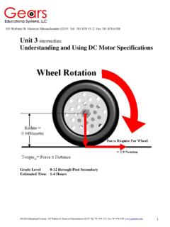
1 GEARS Educational Systems 105 Webster St. Hanover Massachusetts 02339 Tel. 781 878 1512 Fax 781 878 6708 1 Grade Level 8-12 through Post Secondary Estimated Time 1-4 Hours 105 Webster St. Hanover Massachusetts 02339 Tel. 781 878 1512 Fax 781 878 6708 Lesson 3 Understanding and Using DC Motor Specifications GEARS Educational Systems 105 Webster St. Hanover Massachusetts 02339 Tel. 781 878 1512 Fax 781 878 6708 2 Abstract Engineering design success depends in great part on reducing the time spent creating modules, mechanisms and machines. The use of accurate mathematical models can speed up the design process, and minimize the time wasted on trial and error design methods.
2 Trial and error design methods are inefficient and costly. Matching a Motor to a specific application is not easily accomplished through trial and error. Moreover, the necessity of purchasing and testing many dozens of motors is economically wasteful and time consuming. Instead, the best engineering practices employ mathematical models early in the design process. The functional requirements and design parameters of a Motor system can be determined early in the design process and manufacturer s published Motor data can be researched in an attempt to find a suitable match. Designers and engineers use mathematical models to optimize the time spent designing modules, mechanisms and machines by: Reducing the number of possible items in the selection set.
3 Reducing testing and prototyping time Providing a closer match of Motor performance to the functional requirements and design parameters specified early in the design process. This Lesson serves to demonstrate how an Understanding of Motor performance specifications and mathematical models can be used to more closely match the performance of a DC Motor system to a pre-determined specification. This Lesson makes extensive use of the experimental data obtained in the previous Lesson . In addition, students who participate in this Lesson will gain experience in researching manufacturer s published Motor data in an effort to best match a DC Motor system to an existing specification.
4 Objectives Students who participate in this Lesson , and the related activities will: Use experimental data to create mathematical models of Motor performance Use experimentally determined Motor performance data along with manufacturer s published data to make useful predictions about DC Motor performance. Use their Understanding of Newton s laws of motion, torque and rotational speed to compute the performance requirements of a DC Motor system. Use engineering methods and mathematical models in an effort to most closely match DC Motor performance to a given set of functional requirements and design parameters. GEARS Educational Systems 105 Webster St.
5 Hanover Massachusetts 02339 Tel. 781 878 1512 Fax 781 878 6708 3 Terms and Concepts Stall Current Torque Constant Electromotive Force Dynamometer Resistance Radians per Second Voltage Back emf Constant Stall Torque Mass Acceleration Ohm s Law Multimeter No Load RPM Mechanical Advantage Gear Ratio Torque Materials/Equipment/Supplies/Software GEARS-IDS Kit Internet Access Calculator Multimeter (2) Heavy Duty 12V Battery Note: Before beginning this Lesson , it will be necessary to review and understand how to use Ohms Law ( E = I*R ) to calculate voltage (E) when both the current (I) and resistance (R) is given. Using Experimental or Published Data to Create Mathematical Models of Motor Performance Let s look at the data obtained through experiments with the gear head motors supplied in the GEARS-IDS kit.
6 Listed below are the experimental results and the manufacturers published specifications: Stall Current = Amps @ volts (Manufacturers Specs) = Amps/Volt Stall Current = Amperes at volts (Experimental ) = Amps/Volt KE (Voltage constant) = volts/Thousand RPM (Manufacturers Specs) = volts/rad/sec. KE (Voltage constant) = volts/Thousand RPM (Experimental) = volts/rad/sec. KT (Torque Constant) = (Manufacturers Specs) KT (Torque constant) = (Experimental) Note: The Torque Constant KT shown in the table above is called out as but is given instead as Newton-meters/ampere. This is a manufacturer s publishing error that was not addressed at the time of this printing.
7 To convert N-m/Ato simply multiply N-m/A x GEARS Educational Systems 105 Webster St. Hanover Massachusetts 02339 Tel. 781 878 1512 Fax 781 878 6708 4 Use the data from the previous page to make some useful predictions about the DC gear head Motor found in the GEARS-IDS Kit. To do this we must look at a couple of useful algebraic expressions: IKTT = =EKE Where Kt Torque Constant is given in N-m/A (Newton-meters/Ampere) or ( ) KE - Voltage constant is given in volts/radians/seconds or volts/krpm (Volts per Thousand rpm) T - Torque, is given in Nm (Newton-meters) I - Current is given in Amps (Amperes) E - EMF, is given in Volts - Angular velocity, is given radians/sec and/or revolutions per second Remember, when KT (Torque constant) and KE (Voltage constant) are given in Amps/Nm and Volts/Radians/sec respectively, they have the same numerical values.
8 Thus KE (Voltage constant) = KT (Torque constant) volts/rad/sec. = Nm/Ampere Given this information, and the two equations listed above, it is possible to predict the torque of the Motor at any current draw up to stall current. In addition, we can determine the rotational speed (Angular velocity) of the Motor armature at any given voltage. Using the KE (Voltage constant) Suppose you wished to determine the shaft RPM of the Pittman gear head motors used in the GEARS-IDS Kit, at an applied battery voltage of volts? Begin by considering the operation of the Motor . When a fixed magnet DC Motor (With no load acting on it) is connected to a battery the armature will rotate at a speed and direction dependent on the battery voltage and GEARS Educational Systems 105 Webster St.
9 Hanover Massachusetts 02339 Tel. 781 878 1512 Fax 781 878 6708 5polarity. Theoretically the Motor armature should continue to accelerate to a higher and higher speed unless there is a force that works in opposition to the battery voltage. Clearly the Motor armature does not continue to accelerate but instead reaches a finite top speed. The Motor shaft will not continue to rotate faster because the spinning of the armature coils within the permanent magnetic field of the Motor generates a voltage or a back emf that opposes the applied voltage. Under these circumstances there are several forces at work. 1. The forward emf (Voltage) supplied by the battery 2.
10 The back emf (Voltage)generated by the armature spinning within the fixed magnetic field of the Motor . Note: The relationship between the back emf (voltage) and the rotational speed of the armature is given as the KE (Voltage constant). 3. The emf or voltage drop (IxR) across the internal resistance of the armature. The resistance of the armature is relatively slight in comparison to the back emf effect. In order for the Motor armature to continue to spin, a current must continue to pass through the armature windings. The battery voltage must therefore supply enough emf (voltage) to equal both the back emf (voltage) induced within the armature windings as well as the emf (voltage drop) across the armature resistance.