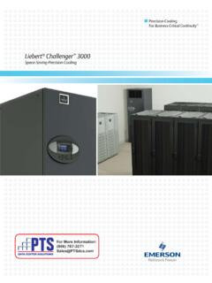
Transcription of Liebert Challenger 3000 with Liebert iCOM - Ottomotores
1 Precision CoolingFor Business-Critical Continuity Liebert Challenger 3000 with Liebert icom Installation Manual - 3 & 5 Tons, 50 & 60Hz iTABLE OF CONTENTSIMPORTANT SAFETY INSTRUCTIONS.. 1 SAVE THESE INSTRUCTIONS .. Descriptions .. Systems .. Water Models .. Systems .. (APPLICABLE TO ALL MODELS).. Preparation.. Inspection .. Considerations.. Handling .. with Skid .. of Skid .. Considerations .. Line .. Supply Water Optional Infrared .. Fluid and Piping Maintenance.. Connections .. Field Connections for Liebert Challenger 3000 Models .. the Air Distribution .. Discharge Systems .. Applications .. Installation .. for Completed Installation .. MODELS SELF-CONTAINED COMPRESSOR .. Location .. Connections .. Voltage .. Voltage .. Lee-Temp /Flood Back Head Pressure Control Condensers .. Piping .. Speed Control Systems.
2 Condenser with Liebert Lee-Temp Flooded Condenser Head PressureControl System .. MODELS SELF-CONTAINED COMPRESSOR .. Considerations .. 36 Regulating Valve .. Valve - 150psig (1034 kPa) System for 3 & 5-Ton Units (Johnson ControlsValve) High Pressure Valve - 350psig (2413kPa) System for 5-Ton Units (JohnsonControls Valve) .. Pressure Valve - 350 psig (2413 kPa) System for 3-Ton Units (Metrex Valve) .. Ball Valve Digital Scroll Compressors .. Control.. MODELS SELF-CONTAINED COMPRESSOR .. Location .. Installation .. Connections .. Voltage .. Voltage .. and Drycooler .. Piping.. Tanks, Fluid Relief Valves and Other Devices.. Instructions.. the System for Filling .. Solutions .. the System .. Ball Valve Digital Scroll Compressors.. Regulating Valve .. Valve - 150psig (1034 kPa) System for 3 & 5-Ton Units (Johnson ControlsValve) High Pressure Valve - 350psig (2413kPa) System for 5-Ton Units (JohnsonControls Valve).
3 Pressure Valve - 350 psig (2413 kPa) System for 3-Ton Units (Metrex Valve) .. Valve Function .. WATER MODELS.. Considerations .. SYSTEM MODELS .. Considerations.. Condensing Units.. Condensing Units .. Connections .. Voltage .. Voltage .. Considerations .. Loop .. Connect Fittings .. Air-Cooled Condensing Units .. Air-Cooled Condensing Units .. the Indoor Condensing Unit.. and Glycol-Cooled Condensing Units.. Considerations .. Water Requirements .. Valve .. Systems .. REFRIGERANT .. Subcooling.. 80 FIGURESF igure 1 Removing the Liebert Challenger 3000 from skid .. 7 Figure 2 Upflow (BU) cabinet dimensions .. 8 Figure 3 Downflow (BF) cabinet dimensions .. 9 Figure 4 Piping connections for air-cooled units - Downflow models .. 11 Figure 5 Piping connections for air-cooled units - Upflow models .. 12 Figure 6 Piping connections for split system fan coil units - Downflow models.
4 13 Figure 7 Piping connections for split system fan coil units - Upflow models .. 14 Figure 8 Piping connections for water/glycol and GLYCOOL units - Downflow models .. 15 Figure 9 Piping connections for water/glycol and GLYCOOL units - Upflow models .. 16 Figure 10 Piping connections for chilled water self-contained units - Downflow models .. 17 Figure 11 Piping connections for chilled water self-contained units - Upflow models .. 18 Figure 12 Electrical connections .. 20 Figure 13 Electrical field connections for Liebert icom .. 21 Figure 14 Air-cooled condensers .. 25 Figure 15 General arrangement Air-cooled models with fan speed control.. 30 Figure 16 General arrangement Air-cooled models with digital scroll and fan speed control .. 31 Figure 17 General arrangement Air-cooled models with Liebert Lee-Temp .. 34 Figure 18 General arrangement Air-cooled models with digital scroll and Liebert Lee-Temp.
5 35 Figure 19 General arrangement Water-cooled models with scroll compressor .. 37 Figure 20 General arrangement diagram Water-cooled models with digital scroll .. 38 Figure 21 Johnson Controls valve adjustment .. 39 Figure 22 Metrex Valve adjustment .. 40 Figure 23 Drycoolers and pump packages .. 48 Figure 24 Pump packages expansion tank .. 49 Figure 25 General arrangement Glycol-cooled models with scroll compressor .. 50 Figure 26 General arrangement Glycol-cooled models with digital scroll .. 51 Figure 27 General arrangement GLYCOOL models with scroll compressor.. 52 Figure 28 General arrangement GLYCOOL models with digital scroll compressor .. 53 Figure 29 Chilled water general arrangement - Upflow (BU).. 55 Figure 30 Chilled water general arrangement - Downflow (BF) models .. 56 Figure 31 Refrigerant piping diagram .. 60 Figure 32 Outdoor air-cooled condensing unit horizontal air discharge models.
6 62 Figure 33 Outdoor air-cooled condensing unit top air discharge models .. 64 Figure 34 Electrical field connections, prop fan condensing module .. 66 Figure 35 Detail of ceiling hanging bracket .. 68 Figure 36 3-ton centrifugal air-cooled condensing unit dimensional data & piping connections .. 69 Figure 37 3-ton centrifugal air-cooled condensing unit (con t.) .. 70 Figure 38 5-ton centrifugal air-cooled condensing unit dimensional data .. 71 Figure 39 5-ton centrifugal air-cooled condensing unit dimensional data (con t.) .. 72 Figure 40 Split systems general arrangement .. 73 Figure 41 3-ton water/glycol-cooled condensing unit .. 75 Figure 42 3-ton water/glycol-cooled condensing unit (con t.) .. 76 Figure 43 5-ton water/glycol-cooled condensing unit dimensional data .. 77 Figure 44 5-ton water/glycol-cooled condensing unit (con t.) .. 78 TABLEST able 1 Unit net weight.
7 7 Table 2 Piping connection size.. 10 Table 3 Recommended free area ft2 (m2) for grilles or perforated panels at output velocities of 550and 600 fpm ( and m/s) .. 22 Table 4 Air-cooled condenser statistics .. 25 Table 5 Recommended line sizes OD copper, inches *.. 27 Table 6 Equivalent lengths (feet) for various pipe fittings .. 27 Table 7 Indoor unit refrigerant charge .. 27 Table 8 Line charges - refrigerant per 100 ft. (30 m) of Type L copper tube .. 27 Table 9 Condenser refrigerant (per serial tag) .. 27 Table 10 Fan speed suction pressure transducer settings .. 29 Table 11 Liebert Lee-Temp suction pressure transducer settings .. 33 Table 12 Refrigerant control settings psi (kPa) .. 40 Table 13 Room dew point temperatures .. 44 Table 14 Indoor unit glycol volume approximate gallons (liters) max.. 45 Table 15 Volume in standard Type L copper piping .. 45 Table 16 Ethylene glycol concentrations.
8 46 Table 17 Mounting hole dimensional data .. 49 Table 18 Drycooler data .. 49 Table 19 Glycol pump data* .. 49 Table 20 Refrigerant control settings psi (kPa) .. 54 Table 21 Unit refrigerant charge .. 59 Table 22 Recommended refrigerant lines (R407C) sizes OD copper .. 60 Table 23 Line coupling sizes .. 60 Table 24 Equivalent lengths (feet) for various pipe fittings .. 60 Table 25 Line charges - refrigerant per 100 ft. (30 m) of Type L copper tube .. 60 Table 26 Horizontal air discharge cabinet and floor planning dimensional data.. 63 Table 27 Horizontal air discharge piping and electrical connection data .. 63 Table 28 Cabinet and floor planning dimensional data - prop fan condensing modules, top airdischarge .. 65 Table 29 Piping and electrical connections - top air discharge .. 65 Table 30 Indoor centrifugal condensing unit .. 67 Table 31 Airflow CFM (CMH) .. 68 Table 32 Water and glycol-cooled condensing unit data.
9 74 Table 33R407C pressure/temperature chart for operation and superheat (discharge/hot gas andsuction gas) .. 79 Table 34R407C pressure/temperature chart for subcooling only (liquid measurements).. 80 Important Safety Instructions1 Liebert Challenger 3000 IMPORTANT SAFETY INSTRUCTIONSSAVE THESE INSTRUCTIONSThis manual contains important safety instructions that should be followed during the installation and maintenance of the Liebert Challenger 3000 . Read this manual thoroughly before attempting to install or operate this qualified personnel should move, install or service this equipment. Adhere to all warnings, cautions and installation, operating and safety instructions on the unit and in this manual. Follow all operating and user instructions.!WARNINGArc flash and electric shock hazard. Disconnect all local and remote electric power supplies and wear protective equipment per NFPA 70E before working within the electrical enclosure.
10 Failure to comply can cause injury or must provide earth ground to unit per NEC, CEC and local codes as proceeding with installation, read all instructions, verify that all the parts are included and check the nameplate to be sure the voltage matches available utility Liebert icom microprocessor does not isolate power from the unit, even in the Unit Off mode. Some internal components require and receive power even during the Unit Off mode of Liebert icom factory-supplied optional disconnect switch is inside the unit. The line side of this switch contains live only way to ensure that there is NO voltage inside the unit is to install and open a remote disconnect switch and check the internal power with a voltmeter. Refer to unit electrical all local codes.!WARNINGRisk of explosive discharge from high-pressure refrigerant. Can cause injury or unit contains fluids and/or gases under high pressure before working with piping.
