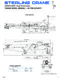
Transcription of LIFTING CHARTS - All Terrain Cranes - Sterling Crane
1 Operating mode " Crane supported" of tipping or danger of overloading occurs boom rope between material handling and installation Overload safety device and Limit blocks and load capacity capacity reduction with folding jib mounted (40 ft - 118 ft) turning speed of the Crane s superstructure with a nominal of symbolsHoisting rope reevingLoad capacity in pounds (lbs)Operating mode Operating types that can only be operated with accessoriesn!Working radius of the telescopic boomWorking radius of the additional jibTelescopic boom length /units of measurementShort codeHoisting rope reevingExtension conditions of the telescopic boom sectionsCounterweight Crane operations " Crane supported"Slewing rangePermissible wind speed of wind Wind influence on the LICCON-overload safety Permissible wind speed and surface susceptibility to wind 1 LTM 1200 FOR USING THE LOAD CAPACITYTABLESDANGER:The specifications contained in the operating instructions are ofvital importance for Crane operation.
2 Failure to observe theseinstructions may lead to ACCIDENTS!LIEBHERR MODEL LTM 1200/1 - 250 TON CAPACITYLIFTING CHARTS - All Terrain load capacity values in the tables are stated in kips. (1 kip = 1000 lbs). working radius is the horizontal gravity center distance of the load from the rota-tional axis of the Crane superstructure measured at the ground. The radius stated isvalid under load conditions, including boom positions not indicated in the load capacity CHARTS are not without a load, the boom may only be moved inside those areas for which loadcapacity values are stated, otherwise there is a danger of tilting. In normal operation,this hazard is prevented by the overload safety device. After switching to "Assembly"mode (with the "assembly" key-operated switch), the boom must not be lowered ortopped outside the range of the working stated load capacities contain the weights of the load bearing, LIFTING and slingingtackle.
3 The possible weight for the load to be lifted is therefore reduced according tothe weights of the afore-mentioned the boomnose is mounted on the jib head during Crane operation, then the possibleload is reduced further corresponding the weight of the boomnose (297 lbs). operating mode " Crane supported" the Crane is raised on its supports, the axle suspension must be sliding arms of the hydraulic support jack must be extended (to a uniform lengthon both sides) to the extent stated in the applirope load capacity sliding arms must be secured by is necessary to place stable underlay material under the support pads of the supportjacks over a large surface area according to ground wheels must be raised clear of the Crane must be aligned horizontally with the aid of the level gauges.
4 The horizon-tal Crane position must be checked occasionally, and if necessary corrected, duringcrane of tipping or danger of overloading occurs slewing platform of an upright Crane is turned away from the forward drivingdirection of the vehicle. Before turning the superstructure, the Crane must be four hydraulic supports of the Crane are not properly supported and in verticalposition, sliding rods are not slid out to the exact measurement specified in the load capa-city CHARTS (on both sides), sliding rods are not secured with pins, support pads are not supported with the appropriate base material (surface area toosmall) for the soil conditions, loads and/or the working radii in the load capacity CHARTS corresponding to the jiblength are exceeded or not met, are operated too close to landfills, basements and slopes, hook load begins swinging due to improper handling, at an angle is executed.
5 Pulling at an angle is most dangerous when it goesagainst the jib length direction. Pulling at an angle is not allowed! 2 LTM 1200 1 (main hoisting gear)Winch 1 is designed for a maximum rope tension of 105 kN. This rope tension mustnot be exceeded under any circumstances. Accordingly, the minimum number of hoi-sting rope lines (rope reeving) should be selected according to the weight of the loadto be lifted (see Table "Hoisting rope reeving" in Chapter II). 2 (Auxiliary hoisting gear)Winch 2 is designed for a maximum rope tension of 105 kN. This rope tension mustnot be exceeded under any circumstances. Accordingly, the minimum number of hoi-sting rope lines (rope reeving) should be selected according to the weight of the loadto be lifted (see Table "Hoisting rope reeving" in Chapter II).
6 Of rope slack When retracting the telescopic boom, the winch must be operated in the direction oflifting simultaneously, in order to prevent the hook block from descending to theground and creating rope slack. The speed of the hoisting rope movement should mat-ched to that used for retraction! The rope guides on the winches must be supervised by a member of the workforcewhen additional equipment is being mounted! rope hoisting rope must be reeved in between boom head and hook block in accor-dance with the maximum rope tension of the winch and the weight of the load to the hoisting rope is reeved multiple times, the efficiency of the hook block isreduced because of pully friction and rope consequence, with a rope tension of 105 kN, only 986 kN (218700 lbs) can bepulled with a 10-fold line reeving, instead of 1050 kN (234000 lbs).
7 The table "Hoisting rope reeving" in Chapter II of this manual for the maxi-mum loads in dependence on the number of hoisting rope number of hoisting rope lines reeved must be set on the control and display unitof the LICCON overload safety device according to the current hoisting rope the block hook is operated with a higher reeve number than necessary for therespective boom lenght loads, then the block hook weight will not be sufficient andcan slacken the cable when lowering, whitch can lead to damage to the LIFTING capacity of the telescopic boom with its 5 extendable telescopic sections islimited. The loads stated in the load capacity tables must not be specifications for the telescopic sections to be extended according to load andrequired boom length must be observed under all a general rule, the boom should first be extended to the required length, and thenloaded.
8 However, it is possible to extend and retract the boom under partial load. Theweight of this partial load is dependent on bearing pad lubrication and the availableuseable lengths of the telescopic without a load, the telescopic boom may only be moved within the workingradius ranges for which values are listed in the load capacity :Failure to observe this regulation may lead to accidents! 3 LTM 1200 between material handling and carrying capacity of the craneThe load carrying members of the Crane have been designed according to the load cri-teria for installation /set up operations (load collective classification = "light" = Q1 orL1). Stress collective S1 according to DIN 15018 Part 3 and stress margin range N1according to DIN 15018 Part 1 or ISO 4301, group an installaton / set up Crane is used material handling, the stress margin rangsincreases.
9 Therefore the loads must be reduced since a higher stress group now beapplicable. This is especially true if the calculated loads are limited by : For Crane value calculation, it has been assumed that the Crane willbe utilized as an installation Crane (load collective classification ="light" = Q1 or L1). If the Crane is also used in material handlingapplication, premature wear of all drive sections must be expected,and cracksmay occur in load carrying steel members. We therefo-restronglyrecommend, that if the Crane is utilized in materialhandling application, the load values are reduced by 50 %, as com-pared to the data given in the corresponding load carrying capa-city details, have material handling data ready and then contact your Liebherr size of the cables as well as drive sections of hoist gears are configured accordingto the load collectives applicable for installation operation (load collective classifica-tion = "light" = Q1 or L1):ISO 4301/2 or 4308/2 Group A1 Hoist gears M3 Intake gears M2If an installaton / set up Crane is used material handling (load collective classification= "light" = Q1 or L1), the stress margin range increases, the rope runs must thereforebe reduced.
10 If this in not assured, then the hoist rope wear out rate will be reachedmuch earlier, and / or the hoist gear must be rebuilt / serviced much refer to the information regarding wear out criteria for ropes according to DIN15020, part 2 or ISO 4309 in chapter "Repeat Crane inspections" in the Crane sOperating :In order to keep wear out rate of hoist ropes as low as possibleduring material handling operation (load collective classification= "medium" or higher) , we recommend the use of a speciallength rope, so thatduring material handling operation the ropeis rolled onto drum of the hoist winch in only one rope layerIf several layers are on the rope drum, the wear rate increases. Inaddition, the winch drive will run cooler, if the Crane is operatedwith only one rope layer.