Transcription of LINEAR BAR GRILLES - Airvector
1 LINEAR BAR GRILLESFor Ceiling, Sidewall, Sill, and Floor InstallationSeries ALB (Architectural LINEAR Bar) GRILLES are designed for installation in the sidewall, sill, floor, and ceiling, and are recommended for supplying heated, ventilated, or cooled air, and for returning or exhausting room air. Their reliable performance assures confident use of cooling temperature differentials up to 25 F at predicted low air motion of 35 fpm in the zone of occupancy. Series ALB GRILLES perform efficiently with air loadings of 1 to 21/2 CFM per and a sound level range of NC 25 to installed in the sidewall near the ceiling, Series ALB GRILLES provide a horizontal pattern above the occupied zone. Core deflections of 15 or 30 direct the air path upward to overcome the drop effect resulting from cool primary air. Use of the deflected cores also improves sight-tightness of the grille installed in the top of a sill or enclosure, Series ALB GRILLES provide a vertical up pattern which is effective in overcoming uncomfortable cold downdrafts and offsetting the radiant effect of glass surfaces.
2 Core deflections of 0 , 15 , and 30 directed toward the glass surface provide upward airflow to the ceiling toward the interior installed in the ceiling, Series ALB GRILLES provide a vertical downward air pattern which is effective in projection heating and cooling the building perimeter from ceiling heights above 12-15 ft. Application of downflow primary air should be limited in volume to insure against excessive drafts at the end of the throw. Core deflections of 0 , 15 , and 30 direct the air path angularly downward as floor installations, GRILLES are specially reinforced. Maximum listed width is 6" for constant traffic areas and areas where heavy loads such as copiers or other equipment may be rolled accross GRILLES . In no case should equipment be "parked" on GRILLES . For occasional traffic areas, maximum listed width is 8". Maximum listed length is 60".
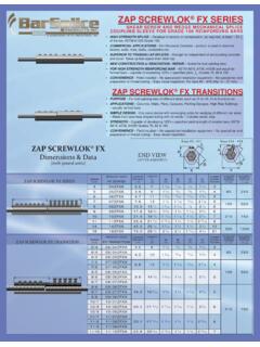
3 Series ALB GRILLES are fabricated of high-quality aluminum extrusions. Components are mechanically interlocked for a blemish-free appearance. Key-ways and splice plates facilitate hair-line butting of 5 ft. sections to form continuous lengths. Opposable Blade Volume dampers are integrally fastened to Series ALB GRILLES . Adjustable Air Equalizing Grids provide spread pattern deflection to shorten the throw. Friction spring fasteners on margins hold GRILLES to duct collar in sill installations. Mitered corner sections are furnished in one SERIES Architecutral LINEAR Bar GrillesALB SERIES Architectural LINEAR Bar Six bar styles including Pencil Proof 0 , 15 , 30 bar deflections Friction margin spring fasteners to hold GRILLES to duct collars for sill installations Extruded Aluminum construction: Mechanical assembly Butts available in continuous lengths with key-way splices.
4 Factory cut or field cut lenghts for precise installation White color default. Available in Black colour, Silver aluminium colour, Brushed & lacquered finish, Mill finish, Primer, Satin Anodized colors and finishes available on Opposable Blade Damper Air Equalizing Grid (min. width 4 ) Removable core Reinforced floor application (max. width 8 ) Mitered corner sections furnished as on pieceMitered Corner ARCHITECTURAL STYLES ALB SERIES2 Rev. 41/2" Spacing, 1/8" Fin ( 0 Defl. )1/8"1/2"21/2"3/16"1/2" Spacing, 3/16" Fin ( 0 Defl. )31/2" Spacing, 3/16" Fin ( 15 Defl. )1/2"3/16"15 461/2" Spacing, 1/4" Fin ( 0 Defl. )1/2"1/4"Pencil Proof1/4" Spacing, 1/8" Fin, ( 0 Defl. )1/8"1/4"1 Bar Styles1/2" Spacing, 3/16" Fin ( 30 Defl. )1/2"3/16"30 5 LISTED SIZES AVAILABLEMin. (no OBD)LxW 6" x 1 1/2" Max. LxW60" x 16"1/8 inch fractional increments in length1/2 inch fractional increments in width (no OBD)1 inch increments in width with OBDS izes longer than maximum will be furnished in multiple sections for field buttingMargin StylesNo FasteningN/A with -F, -GN/A with -A, -B, -GFastening Method-1-2-3 Spring clipScrewN/A with Bar Style 1N/A with -F, -G Min Width 4 -4 Concealed-5 Core spring clipsOnly with combined -F & -RM optionsAll dimensions in " maximum width for constant traffic.
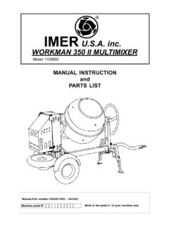
5 8" maximum width for occasional ALB products include a 1/32" tolerance for thermal expansion based on a +40 F temperature every +20 F differential above +40 F, reduce required listed length by 1/64" per 5 feet of RF Reinforced Floor Application(Up to 8 wide for occasional traffic)- RM Removable Core ApplicationOnly w/ -F, -G- GK Frame GasketHOW TO ORDER ALB SERIESALB1048 -F1/8 Bar, 1/4 Spacing, 0 .. with OBD1/8 Bar, 1/2 Spacing, 0 .. with OBD3/16 Bar, 1/2 Spacing, 0 .. with OBD3/16 Bar, 1/2 Spacing, 15 .. with OBD3/16 Bar, 1/2 Spacing, 30 .. with OBD1/4 Bar, 1/2 Spacing, 0 .. with OBDALB10 ALB17 ALB20 ALB27 ALB30 ALB37 ALB40 ALB47 ALB50 ALB57 ALB60 ALB67 MODEL SERIESMARGIN STYLEN arrow Flange (3/8 )Rounded Edge (13/16 )Flat Flange (1 )Standard Floor Frame (1 )Narrow Floor Frame (3/16 )Beveled Flange (1 )T-Bar Margin (1 )-A-B-E-F-G-R-T -1 FASTENINGNo FasteningSpring ClipsScrew FasteningConcealed MountingRemov Core Spring Clips-1-2-3-4-5 LENGTH (INCHES)WIDTH (INCHES /MFINISHSee chart4 -RMMISCELLANEOUS OPTIONSV ertical BarsAir Equalizing GridReinforced for FloorRemovable CoreFrame Gasket-V-L-RF-RM-GK- LAir Equalizing Grid(Minimum 4 wide))
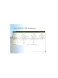
6 Listed + 9/32"9/16"-AN/A with -3, -RM1 9/16"Listed - 1/4"7/8"-BN/A with -3, -RMListed + 7/8"1 9/32"Listed - 1/4"-EListed + 1 1/4"1 9/32"N/A with -RM1 1/16"Listed - 1/4"-F1"2"Only with -RM, N/A with -2, -4 Listed + 1 3/8"Listed - 1/4"-GOnly with -1, -RM3/16"2"Listed - 1/4"Listed - 1/4"N/A with -RM-RListed + 1 1/4"1 9/32"1 1/16"Listed - 1/4"-TN/A with -2, -3, -4, -RMListed1 9/32"Listed - 11/2"1"Min. with OBDLxW6" x 3"ALB SERIESM odify Table 1 by listed values for grillelengths above (T) ' - 6'7' - 20'21' - 100'+ 0+ 5+ 10No ChangeT x x Throw-Sidewall in Table 1(or factor in Table 2 if used) by listed 1 Case 2T x x .90T x .60 CoolingVentilatingHeatingT x .70T x .60T x .40 Listed Width in "2" "3"4"5"6"8"10"12"14"16"18"20"24"30"36". m (1') m (5') 2 AIR MEASUREMENTSUPPLYRETURN2220A VELOMETER JET VK VELOCITY(1")@-18 C T@ 0 F T@-29 C T@-20 F T@-4 C T@+25 F T@ -18 F T@ 0 F T@ -29 C T@ -20 F T@ -4 C T@+25 F TNOTES:a.
7 Table 1 based on 4 ft. grille length. For longer lengths, correct throw and NC per Table When using continuous grille lengths with alternate active and inactive sections, a reduction in throw can be obtained by omitting the factors contained in table Bar style 1: Increase Table 1 NC + 5 Supply air temperature effect on horizontal throw is shown in table 3. Vertical down-throw at varying supply temperatures is shown in Table When spreading the air path with horizontal deflection of 22 per side in grille lengths up to 4 ft.: Multiply Table 1 Throw x .75 Increase Table 1 NC x 5 NC Multiply Table 1 PS x Multiply Table 5 AK x .90f. Terminal velocities (VT) at the minimum and maximum Throw (T) values are rated at 125 FPM and 75 FPM respectively with corresponding room velocities (VR) of 50 fpm and 35 2 CONTINUOUS GRILLE LENGTH FACTORSTABLE 4 VERTICAL DOWN-THROW and Supply Air Temperature Supply FactorsTABLE 5 SUPPLY GRILLES AREAS Per Ft.
8 Of LengthMultiply Throw in Table 1(or factor in Table 2 if used) by listed x x x 3 SUPPLY AIR TEMPERATURE FACTORSENGINEERING PERFORMANCE PERFORMANCE D ATAALB SERIESCFMperFootListedWidthinInchesMin. PS in H2 OBar StyleBar Style2 & 3 & 4 & 51 & 62 & 3 & 4 & 51 & 6 Outlet Velocity (VK) FPMT hrow (T) in FeetMinimum Ceiling Heightin @-18 F T@-25 F T203040506070809010012014016018020025030 035040011/211/2211/2221/211/2221/23221/2 34221/234221/23421/234521/23453456 3456 456845684568 <. <. <. <. <. <20302520<20303025<203030252030302520303 0252030302520353025203530252035302520403 530254035302540353025403530454035< Velocity (VK) FPMT otal Pressure (PT) Inches H2 OTABLE 1 SUPPLY AIRSYMBOLSVT Terminal Velocity in fpmVR Room Velocity in fpmVK Outlet Velocity in fpmAK Outlet area in Sq. FeetAN Neck Area in Sq. Ft. PS Static Pressure H2 ONC Re 8db Room attenuationT Throw in feet at X and Y T Temperature Differential1'T21/2'6'VT VR VKSILLT6' VKSIDEWALLVT PERFORMANCE DATAALB SERIESTABLE 2 RETURN AIR - CFM Per Foot of Length11/2221 2520403550456555907512010014512040356555 8570105901501251901602402004540706095801 2010016514021518026522055459075115100145 1202051702602203252706555100851351151651 40235195305255375315 ListedWidthinInchesAKAreaBarStyleCFMCFMC FMCFMCFMCFMNC 20-25 Non-DuctedNC 25-30 DuctedNC " " " " " " 2001652552153102604303505454456605408206 7010108203252704153505104257005708857301 0808801335109016451335360305465390565475 7856359908151210985149512251835149044537 0570475695580960780122010001475120018251 5002250182551543065555080067011009001410 1160171013902110173526002110 ListedWidthinInchesAKAreaBarStyleCFMCFMC FMCFMCFMCFMNC 20-25 Non-DuctedNC 25-30 DuctedNC " " " " " " PSSYMBOLSVT Terminal
9 Velocity in fpmVR Room Velocity in fpmVK Outlet Velocity in fpmAK Outlet area in Sq. FeetPT Total Pressure H2O PS Static Pressure H2 ONC Re 8db Room attenuationT Throw in feet at X and Y T Temperature PERFORMANCE D TO SPECIFY ARCHITECTURAL LINEAR BAR GRILLES AND REGISTERSS upply RegisterSupply and mounting of LINEAR bar register with attached opposed blade damper and 45 degree mitered corners, series ALB. Constructed from extruded aluminum, manufactured by GrilleSupply and mounting of LINEAR bar grille with 45 degree mitered corners, series ALB. Constructed from extruded aluminum, manufactured by Airvector .