Transcription of Linear Tolerances Limits & Fits - Institute of …
1 IT,Sligo Computer Aided design Tolerances 1 Linear Tolerances Limits & fits Manufacturing is principally concerned with ensuring the functionality, interchangeability and quality of the parts and products that have been designed. Designers must recognise that manufactured parts will vary somewhat from the original design and that it is not possible to repeatedly machine components to exact nominal dimension. Therefore design acceptable Tolerances must be determine which indicate how much the part can safely vary while still maintaining acceptable function, and these Tolerances must be communicated on the drawings. When dimensioning a part drawing, Linear Tolerances are used on the functional features of the part to specify the Tolerances that are allowable.
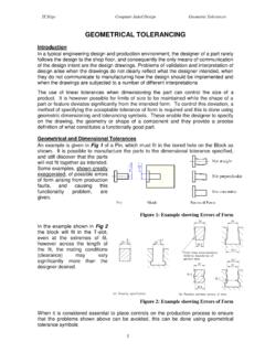
2 General Tolerances : In precision engineering , dimensions which only show the nominal size are controlled by a general tolerance . This will normally apply to non-functional dimensions or where accuracy is not critical. The general tolerance may be shown as a statement on a company s standard drawing sheet such as All dimensions to be correct within , unless otherwise stated . Alternately a general tolerance may be applied in more detail, either depending on the accuracy or where the tolerance relates to the number of decimal places. If a general tolerance of was applied to the pin shown opposite in Fig 1, the overall length of the pin could vary between mm and and still be acceptable.
3 The main diameter of the pin could also vary from to and therefore to guarantee that the pin would fit in a hole, the hole would need to be machined to the maximum size ( ). Fig 1: Pin In some cases it may be necessary to place tighter control on the accuracy of a particular feature than the general tolerance , and this may be done by including a symmetrical tolerance to the dimension on the drawing (see the 50mm dimension shown opposite). If the tongue shown in Fig 2 is to slide longitudinally in the slot, then using a general tolerance could result in the tongue being larger than the slot and not being able to slide.
4 The tongue and slot are shown at (b) dimensioned for satisfactory functioning, where even if the slot is machined as small as possible and the tongue as large as possible, there will still be a clearance fit and the tongue will slide. Fig 2: Tongue and Slot IT,Sligo Computer Aided design Tolerances 2 Standard fits : As designers recognise that manufacturing must be told how much a part may deviate from the nominal size while still functioning as intended, and due to the necessity for interchangeabilty, a system of Limits and fits has been developed. While the system is used for all shapes and types of fit, the terminology uses a shaft and hole to define the principles.
5 Some of the basic terminology is shown below in Fig 3. Fig 3: Terminology Types of Fit: A fit is defined as the working condition between a mating shaft and hole and as we can neither manufacture nor measure to an exact size, the shaft is deemed to always be either larger or smaller than the hole. There are three basic types of fits specified: Clearance fits : This gives a condition in which the shaft is smaller than the hole. Interference fits : This gives a condition in which the hole is smaller than the shaft. Transition fits : This may provide either clearance or interference at the extremes of fit. Fig 4: Types of fits IT,Sligo Computer Aided design Tolerances 3 Limits & fits : When designing an engineering product the fit required and the appropriate tolerance must be determined.
6 For example, a gear located on a shaft might require an interference fit where the shaft is larger than the gear hub, so as to assist in the transmission of the torque. Alternatively for a plain journal bearing the shaft must be smaller than the hole in order to allow rotation. Rather than individual designers deciding on the variability in size for the hole and shaft dimensions, a standard system has been developed which defines a range of Tolerances and this is now universally accepted and used. The ISO system of Limits and fits specifies twenty-eight fundamental deviations for holes, twenty-eight fundamental deviations for shafts and assigns eighteen grades of tolerance .
7 This provides an enormous amount of hole and shaft Tolerances and a huge number of fits or mating conditions, which can cater for a wide range of engineering situations. However, experience shows that the majority of fits required for normal engineering can be provided by a small selection of these Tolerances . Fundamental Deviation The fundamental deviation refers to the location of the tolerance with respect to the zero line (basic/nominal size). Capitol letters are used for holes and lower case letters are used for shafts. Fig 5: (a) Fundamental Deviations Holes (b) Fundamental Deviations shafts For holes the letters A to G represent oversize holes, while the letters N to ZC represents undersize holes.
8 For shafts the letters a to g represent undersize shafts, while the letters m to zc are for oversize shafts. It should be noted that H (holes) and h (shafts) have a fundamental deviation of zero and therefore are commonly used for one or other of the components of a fit (hole basis system or shaft basis system). Fig 6: Full range of Fundamental Deviations IT,Sligo Computer Aided design Tolerances 4 Grade of tolerance : The grade refers to the width of the tolerance band (actual magnitude of the tolerance ), and is represented by a number. There are 18 grades of tolerance , which are allotted the numbers IT01, IT0, IT1.
9 IT16. Fine grades are referred to by the first few numbers. As the numbers get larger, so the tolerance zone becomes progressively larger as shown graphically in Fig 7. The actual magnitude of the tolerance is dependant on the feature size and is found using tables of Limits and fits . Fig 7: tolerance Grades Selected ISO fits : The majority of fits required for normal engineering can be provided by a small selection of Tolerances and the following hole and shaft Tolerances have been found to be commonly applied. Selected hole Tolerances : H7, H8, H9, H11 Selected shaft tolernaces: c11, d10, e9, f7, g6, h6, k6, n6, p6, s6 The attached data sheet of Selected ISO fits shows the range of fits derived from these Tolerances and covers a range, from loose clearance to heavy interference fits .
10 fits EXAMPLES H11-c11 Slack running fit Used to give flexibility under load, easy assembly or a close fit at elevated temperatures. engine exhaust valve in guide H9-d10 Loose running fit Used for gland seals, loose pulleys and very large bearings. Idler gear on spindle H9-e9 Easy running fit Used for widely separated bearings or several bearings in line. Camshaft in bearing H8-f7 Normal running fit Suitable for applications requiring a good quality fit that is easy to produce. Gearbox shaft in bearing H7-g6 Sliding and location fit Suitable for precision and location fits . Valve mechanism link pin H7-h6 Location fit Suitable for many non-running assemblies.