Transcription of Liquid Stream Fundamentals: Aeration Design - WEF Home
1 Introduction Biological treatment of organic material and ammonia requires ample oxygen to facilitate degradation and removal. However, minimal Dissolved Oxygen (DO) is typically present in raw wastewater, and must be added to the treatment process to enhance and facilitate biological removal of soluble organic material and ammonia . Water Resource Recovery Facilities (WRRFs) rely on Aeration systems to transfer oxygen from a gaseous state to a dissolved Liquid form that is available to support biological treatment. Aeration can be provided through mechanical agitation of the Liquid surface to entrain DO in the Aeration tanks (mechanical Aeration ) or through introducing oxygen into the Aeration tanks through porous devices (diffused Aeration ). Aeration systems are designed to increase the air-water interface within a process Liquid , allowing for sufficient oxygen transfer required to support the biological processes.
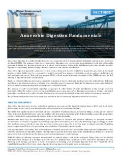
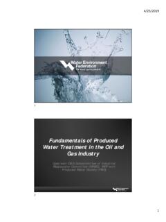
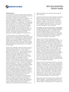
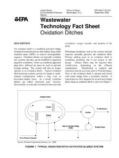
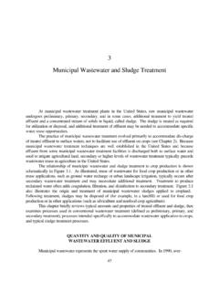
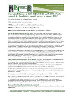
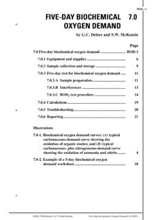
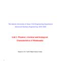
2 Mechanical Aeration consists of motor-driven impellers, propeller aspirators, or rotors that generally operate at the Liquid surface to provide DO within the Aeration tanks. The impeller and rotor transfer oxygen by mixing the Liquid surface while the propeller aspirator injects atmospheric air into the Liquid . The equipment used depends on which configuration was utilized for the treatment process. There are four general configurations for mechanical Aeration systems: radial flow low speed, axial flow high speed, horizontal rotors, and aspirating devices. Radial flow low speed and axial flow high speed utilize impellers that can be designed at the Liquid surface or submerged at varying depths (see Figures 1 and 2). Horizontal rotors utilize horizontal impellers (rotors) to agitate the Liquid surface and deliver oxygen to the Aeration tanks (see Figure 3). Aspirating devices utilize a propeller aspirator which can be positioned at various angles to reach distinct levels for Aeration mixing (see Figure 4).
3 The Standard Aeration Efficiency (SAE) of each configuration is dependent upon the Design of the equipment used (impeller, rotor, or propeller aspirator), tank geometry, effects of adjacent walls, input power to tank volume, and various other factors [1]. Liquid Stream Fundamentals: Aeration Design This fact sheet covers an overview of diffused and mechanical Aeration , basic concepts of Aeration Design , the parameters and correction factors utilized in Aeration Design calculations, and Aeration Design considerations as well as solutions. FACT SHEET Copyright 2017 Water Environment Federation. All Rights Reserved. 1 WSEC-2017-FS-024 Municipal Resource Recovery Design Committee Liquid Stream Fundamentals: Aeration Design Figure 1 Radial flow low speed surface aerator [2]. Figure 2 Axial flow submerged turbine aerator (left) and radial flow submerged turbine aerator (right) [1]. Diffused Aeration systems typically consist of mechanical equipment including blowers, air piping and diffusers, that work in conjunction with instrumentation and controls to deliver oxygen as required to support the biological processes.
4 Ambient air is compressed and introduced via submerged diffusers to distribute gaseous air bubbles in the process Liquid (see Figures 5 and 6). Fine pore diffusers create smaller bubbles which maximize the air-water interface, and subsequently allow for greater oxygen transfer from the air to the Liquid . Once in Liquid form, the oxygen is available for use by the biological process. Refer to the Aeration Diffuser Fundamentals and the Aeration Blower Fundamentals Fact Sheets for additional information regarding the mechanical components that comprise diffused Aeration systems. Atmospheric air is commonly used for both mechanical and diffused Aeration purposes at WRRFs, as it is an abundant, easily accessible resource. Ambient, atmospheric air, is comprised of approximately 21% oxygen (depending on the altitude).
5 Alternatively, pure oxygen, or high-purity oxygen (HPO) can also be used for Aeration ; however, considering the operations and maintenance costs of oxygen generation systems and/or commercially available bulk oxygen, the use of HPO for Aeration is less common [1]. WRRFs may also draw foul air from the headspace of process tanks or from odorous buildings such as preliminary treatment facilities for odor control, and use that air for Aeration of biological processes. Odorous air, however, contains compounds that could potentially lead to corrosion of Aeration equipment, and if odorous air is used for Aeration , careful consideration for compatible materials must be included in the selection and Design of Aeration equipment. Copyright 2017 Water Environment Federation.
6 All Rights Reserved. 2 WSEC-2017-FS-024 Municipal Resource Recovery Design Committee Liquid Stream Fundamentals: Aeration Design Figure 3. Horizontal rotor [1][2]. Figure 4. Aspirating device [1][2]. Atmospheric air intake Propeller Dissolved Oxygen Figure 5. Coarse bubble diffuser in diameter [2] Figure 6. Fine bubble diffuser in diameter [2] Aeration System Design Design of Aeration systems generally includes selecting equipment and developing controls that will allow for the delivery of oxygen as required to support the biological treatment system. The first step in designing an Aeration system is to determine the oxygen demand. Although process model simulations aid in determining oxygen demand and Aeration requirements, it is important to understand the factors that influence oxygen demand and how oxygen demand is calculated. The amount of air required to support the biological process is also known as the Actual Oxygen Requirement (AOR), and is given in terms of mass per time ( lbs O2/day).
7 The following considerations factor into calculation of the AOR: Design Flows and Loads. Establishing the correct flow and load criteria is imperative to the success of the aerationsystem Design . In general, the Aeration system must be capable of providing sufficient oxygen under minimum,average and peak demand conditions. Design guidelines recommend accounting for the 24-hour demand of theaverage day of the peak month when calculating the maximum Aeration requirements [1]. Requirements for Carbonaceous Biochemical Oxygen Demand (cBOD) Removal. The mass of oxygen required to satisfy carbonaceous oxidation can be approximated for preliminary Design assuming a range of to lb O2 is required per pound of cBOD removed [3]. The amount of oxygen per mass cBOD removed is dependent on the Solids Retention Time (SRT) of the process, and processes operated at a longer SRT require more oxygen per mass of cBOD due to endogenous respiration.
8 Equation in WEF MOP 8 or Figure 5-4 in the USEPA Fine Pore Aeration Design Manual can be used to estimate the carbonaceous oxygen demand applied to actual Aeration system Design [1][4]. The reaction of carbonaceous oxidation and removal can be found below [5]: oxidation and synthesis: Endogenous respiration: Requirements for Total Nitrogen Reduction. Oxygen demand to satisfy nitrification needs to be considered in additionto the oxygen demand required for carbonaceous oxidation for systems which provide ammonia removal orotherwise nitrify. In general, lb of O2 is required per pound of ammonia oxidized to nitrate [1]. Equation of WEFMOP 8 should be used to calculate the oxygen demand required for nitrification . The reaction for oxidation ofammonia to nitrate can be found below:Once the AOR is calculated, the Standard Oxygen Requirement (SOR) can be estimated. The SOR is the amount of oxygen that needs to be transferred to meet the AOR after adjusting for the environmental conditions within the Aeration tank.
9 The SOR value is used to determine the air demand required to deliver sufficient oxygen to the process Liquid . The air demand, given in terms of standard cubic feet per minute (scfm), is calculated by accounting for the specific weight of air at standard temperature, as well as the mass fraction of oxygen in air. Additionally, the Standard Oxygen Transfer Efficiency (SOTE) of the Aeration equipment must be applied to the air demand calculation. The SOTE varies depending on the Aeration equipment as well as the air flux applied to the diffuser, with fine bubble diffusers exhibiting higher SOTE values (~2%/ft submergence) compared with coarse bubble diffusers (< 1%/ft submergence) and jet aerators (between < 1%/ft and 2%/ft submergence) [1]. Air demand calculations must also account for the quantity of air required to maintain biomass in suspension. The volume of air required to provide sufficient mixing depends on a variety of factors, including the tank geometry and the biomass concentration.
10 The tank geometry is a key factor to consider because typically the back of the Aeration tank receives a limited amount of mixing, especially if a tapered grid system is utilized. In suspended growth Aeration systems, the air Copyright 2017 Water Environment Federation. All Rights Reserved. 3 WSEC-2017-FS-024 Municipal Resource Recovery Design Committee Liquid Stream Fundamentals: Aeration Design demand for mixing is typically less than that required for oxygen transfer to support biological processes. In fixed growth and Integrated Fixed-Film Activated Sludge (IFAS) biological processes, mixing requirements often exceed process Aeration requirements due to the fixed or floating media added to the Mixed Liquor Suspended Solids (MLSS) that promotes additional biological growth. However, the air demand requirements for mixing should still be compared with the air demands for oxygen transfer across all of the zones of an Aeration tank to ensure that sufficient mixing air is provided.