Transcription of Listing Report ELC 1917 - ICC Evaluation Service
1 Listings are not to be construed as representing aesthetics or any other attributes not specifically addressed, nor are they to be construed as an endorsement of the subject of the Listing or a recommendation for its use. There is no warranty by ICC Evaluation Service , LLC, express or implied, as to any finding or other matter in this Listing , or as to any product covered by the Listing . Copyright 2020 ICC Evaluation Service , LLC. All rights reserved. Page 1 of 10 ICC-ES Listing Report ELC-1917 Reissued September 2020 This Listing is subject to renewal September 2021. | (800) 423-6587 | (562) 699-0543 A Subsidiary of the International Code Council CSI: DIVISION: 03 00 00 CONCRETE Section: 03 16 00 Concrete Anchors DIVISION: 05 00 00 METALS Section: 05 05 19 Post-Installed Concrete Anchors product Certification System: The ICC-ES product -certification system includes evaluating reports of tests of standard manufactured product , prepared by accredited testing laboratories and provided by the listee, to verify compliance with applicable codes and standards.
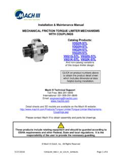
2 The system also involves factory inspections, and assessment and surveillance of the listee s quality system. product : Hilti Kwik Bolt TZ (KB-TZ) Carbon and Stainless Steel Anchors in Cracked and Uncracked Concrete Listee: HILTI, INC. Compliance with the following standards: Annex D, Anchorage of CSA (-14, -04), Design of Concrete Structures, CSA Group. Compliance with the following codes: Hilti Kwik Bolt TZ (KB-TZ) Carbon and Stainless Steel Anchors in Cracked and Uncracked Concrete, as described in this Listing Report , are in conformance with CSA (-14, 04), Annex D, as referenced in the applicable section of the following code editions: National Building Code of Canada 2015 and 2010 Applicable Section: Division B, Part 4, Section Description of anchors: KB-TZ anchors are torque-controlled, mechanical expansion anchors. KB-TZ anchors consist of a stud (anchor body), wedge (expansion elements), nut, and washer.
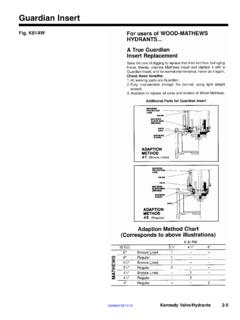
3 The anchor (carbon steel version) is illustrated in Figure 1. The stud is manufactured from carbon steel or AISI Type 304 or Type 316 stainless steel materials. Carbon steel KB-TZ anchors have a minimum 5 m zinc plating. The expansion elements for the carbon and stainless steel KB-TZ anchors are fabricated from Type 316 stainless steel. The hex nut for carbon steel conforms to ASTM A563-04, Grade A, and the hex nut for stainless steel conforms to ASTM F594-09. The anchor body is comprised of a high-strength rod threaded at one end and a tapered mandrel at the other end. The tapered mandrel is enclosed by a three-section expansion element which freely moves around the mandrel. The expansion element movement is restrained by the mandrel taper and by a collar. The anchor is installed in a predrilled hole with a hammer. When torque is applied to the nut of the installed anchor, the mandrel is drawn into the expansion element, which is in turn expanded against the wall of the drilled hole.
4 ELC-1917 | Most Widely Accepted and Trusted Page 2 of 10 FIGURE 1 HILTI CARBON STEEL KWIK BOLT TZ (KB-TZ) Identification: 1. The anchors are identified by packaging labeled with the manufacturer s name (Hilti, Inc.) and contact information, anchor name, anchor size, and Listing number (ESL-1067), and the ICC-ES Listing mark. The anchors have the letters KB-TZ embossed on the anchor stud and four notches embossed into the anchor head, and these are visible after installation for verification. Table 2 and Figure 4 summarizes the length code identification system. 2. The Report holder s contact information is the following: HILTI, INC. 7250 DALLAS PARKWAY, SUITE 1000 PLANO, TEXAS 75024 (800) 879-8000 Installation: Installation parameters are provided in Figures 2 and 3 and Tables 1A and 1B. Anchor locations must comply with this Listing Report and plans and specifications approved by the authority having jurisdiction.
5 The Hilti KB-TZ must be installed in accordance with manufacturer s published instructions and this Listing Report . In case of conflict, this Listing Report governs. Anchors must be installed in holes drilled into the concrete using carbide-tipped masonry drill bits complying with ANSI or using the Hilti SafeSet SystemTM with Hilti TE-YD or TE-CD Hollow Drill Bits complying with ANSI with a Hilti vacuum with a minimum value for the maximum volumetric flow rate of 129 CFM (61 l/s). The Hollow Drill Bits are not permitted for use with the 3/8 and 3/4 diameter KB-TZ anchors. The minimum drilled hole depth, h0, is given in Tables 1A and 1B. When drilling dust is not removed after hole drilling, make sure to drill deep enough to achieve hnom, taking into account the depth of debris remaining in the hole. If dust and debris is removed from the drilled hole with the Hilti TE-YD or TE-CD Hollow Drill Bits, compressed air or a manual pump, hnom is achieved at the specified value of h0 noted in Tables 1A and 1B.
6 The anchor must be hammered into the predrilled hole until hnom is achieved. The nut must be tightened against the washer until the torque values specified in Tables 1A and 1B are achieved. The 3/8 , 1/2 , and 5/8 anchors may be installed using the Hilti Safe-Set System consisting of the Hilti SIW-6AT-A22 Impact Wrench used together with the Hilti SI-AT-A22 Adaptive Torque Module in accordance with the manufacturer s published installation instructions as shown in Figure 3A. FIGURE 2 KB-TZ INSTALLED washer expansion element bolt hex nut dog point collar mandrel UNC thread anch da dh hef ho t thread unthr hnom ELC-1917 | Most Widely Accepted and Trusted Page 3 of 10 3/8 Diameter 1/2 Diameter 5/8 Diameter 3/4 Diameter FIGURE 3 INSTALLATION INSTRUCTIONS ELC-1917 | Most Widely Accepted and Trusted Page 4 of 10 FIGURE 3A INSTALLATION INSTRUCTIONS USING SI-AT-A22 ADAPTIVE TORQUE SYSTEM ELC-1917 | Most Widely Accepted and Trusted Page 5 of 10 Hilti SafeSet System with Hollow Drill Bit Hilti TE-CD or TE-YD Hollow Carbide Drill Bit with a Hilti Vacuum (per section ) Hilti SafeSet System with the Adaptive Torque Tool Hilti SIW-6AT-A22 Impact Wrench with the Hilti SI-AT-A22 Adaptive Torque Module Hilti Dust Removal Systems Hilti Rotary Hammer Drill with DRS (Dust Removal System)
7 Module Hilti TE DRS-D Dust Removal System with Hilti Vacuum FIGURE 3B HILTI SYSTEM COMPONENTS Ultimate Limit States Design: Design resistance of anchors for compliance with the 2015 NBCC must be determined in accordance with CSA Annex D and this Listing Report . Design resistance of anchors for compliance with the 2010 NBCC must be determined in accordance with CSA Annex D and this Listing Report . Design parameters provided in Tables 3 and 4 of this Listing Report are based on the 2015 NBCC and 2010 NBCC (CSA and CSA ). The limit states design of anchors must comply with CSA or CSA , as applicable, except as required in CSA or CSA , as applicable. Material resistance factors must be c = and s = in accordance with CSA (-14, 04) Sections and , and resistance modification factor, R, as given in CSA Section , or CSA Section , as applicable, and noted in Tables 3 and 4 of this Listing Report , must be used for load combinations calculated in accordance with Division B, Part 4, Section of the 2015 NBCC, Division B, Part 4, Section of the 2010 NBCC, or Annex C of CSA or Annex C of CSA , as applicable.
8 The factored steel strength Nsar or Vsar, in tables 3 and 4 of this Listing Report have been multiplied by s and R to determine the factored resistance. The factored pullout strengths Ncpr,uncr, Ncpr,cr or Ncpr,eq in Tables 3 and 4 of this Listing Report have been multiplied by c and R to determine the factored resistance. ELC-1917 | Most Widely Accepted and Trusted Page 6 of 10 Requirements for Factored Pullout Resistance in Tension: The factored pullout resistance of a single anchor in accordance with CSA and , or CSA and , as applicable, in cracked and uncracked concrete, Ncpr,cr and Ncpr,uncr, respectively, is given in Tables 3 and 4. For all design cases, c,P = In accordance with CSA , or CSA , as applicable, the factored pullout resistance in cracked concrete may be calculated in accordance with the following equation: , , = , (N, MPa) (Eq-1) In regions where analysis indicates no cracking in accordance with CSA , or CSA , as applicable, the factored pullout resistance in tension may be calculated in accordance with the following equation: , , = , (N,MPa) (Eq-2) Where values for Ncpr,cr or Ncpr,uncr are not provided in Table 3 or Table 4, the pullout resistance in tension need not be evaluated.
9 Requirements for Critical Edge Distance: In applications where c < cac and supplemental reinforcement to control splitting of the concrete is not present, the concrete breakout resistance in tension for uncracked concrete must be calculated in accordance with CSA or CSA , as applicable. In lieu of using CSA , or CSA , as applicable, values of cac must comply with Table 3 or Table 4. TABLE 1A SETTING INFORMATION (CARBON STEEL ANCHORS) SETTING INFORMATION Symbol Units Nominal anchor diameter (in.) 3/8 1/2 5/8 3/4 Anchor da in. (mm) ( ) ( ) ( ) ( ) Nominal bit diameter dbit in. 3/8 1/2 5/8 3/4 Effective min. embedment hef mm 38 51 70 51 83 79 102 83 95 121 Nominal embedment hnom mm 46 59 78 60 91 91 113 97 110 136 Min. hole depth ho mm 51 67 86 67 102 95 121 102 114 146 Min. thickness of fastened part1 tmin mm 0 0 0 19 6 9 19 0 0 23 Required Installation torque Tinst Nm 34 54 81 149 Min. dia. of hole in fastened part dh mm Standard anchor lengths anch mm 76 95 127 95 114 140 178 121 152 216 254 140 178 203 254 Threaded length (incl.)
10 Dog point) thread mm 38 57 93 41 60 86 124 38 70 133 171 63 103 128 179 Unthreaded length unthr mm 39 54 83 77 1 The minimum thickness of the fastened part is based on use of the anchor at minimum embedment and is controlled by the length of thread. If a thinner fastening thickness is required, increase the anchor embedment to suit. ELC-1917 | Most Widely Accepted and Trusted Page 7 of 10 TABLE 1B SETTING INFORMATION (STAINLESS STEEL ANCHORS) SETTING INFORMATION Symbol Units Nominal anchor diameter (in.) 3/8 1/2 5/8 3/4 Anchor da in. (mm) ( ) ( ) ( ) ( ) Nominal bit diameter dbit in. 3/8 1/2 5/8 3/4 Effective min. embedment hef mm 51 51 83 79 102 95 121 Nominal embedment hnom mm 59 60 91 91 113 110 136 Min. hole depth ho mm 67 67 102 95 121 114 146 Min. thickness of fastened part1 tmin mm 6 19 6 9 19 3 41 Required Installation torque Tinst Nm 34 54 81 149 Min. dia. of hole in fastened part dh mm Standard anchor lengths anch mm 76 95 127 95 114 140 178 121 152 216 254 140 203 254 Threaded length (incl.