Transcription of Lithium Plating in Lithium -Ion Cells - NASA
1 Lithium Plating in Lithium -Ion Cells Albert H. Zimmerman and Michael V. Quinzio The Aerospace Corporation Presented at the NASA Battery Workshop 16-18 November 2010. Huntsville, AL. The Aerospace Corporation 2010. Introduction What is Lithium Plating ? Lithium metal that has been deposited on the surface of the anode, but has not moved into the carbon intercalation sites Carbon sites could be filled (or nearly filled). Lithium metal deposited more rapidly than intercalation can occur Why is Lithium Plating bad? Lithium capacity is lost from the cell; can give rapid capacity loss Lithium metal can become isolated from the anode surface, leaving conductive metal to accumulate in the separator Eventually continued Lithium Plating can cause a metallic path to form through the separator to give a short circuit Changes in cell compression (material volume expansion or end plate tightening) could allow the metal deposits in the separator to short circuit the cell.
2 How can we reliably detect and avoid metallic Lithium Plating ? 2. Types of Metallic Lithium Plating Homogeneous Lithium Plating Occurs over large areas of anode within cell Can result from the carbon becoming completely filled with Li Can result from high charge current (excessive deposition rate). Can result from low temperature (slow intercalation rate). Heterogeneous or localized Lithium Plating Can occur around any non-uniformity in the cell that redirects the current away from a direct path from the cathode to the anode during charge Most often seen at edges, corners, around particles, or separator wrinkles Typically linked to cell design or stack defects Exacerbated by the conditions causing homogeneous Plating Real cell Lithium Plating probably includes aspects of both homogeneous and heterogeneous Plating 3.
3 What Can Cell Models Tell Us About Li Plating ? We use a 3-D finite element model of a prismatic cell Includes all the processes known to occur in Li-ion Cells Described in: A. H. Zimmerman and M. V. Quinzio, Method for Predicting the Reliability of Lithium -Ion Batteries, Presented at the 2008 Power Sources Conference, Philadelphia, PA, June 2008, paper 25-1. Modeling tells us when Li Plating can occur during charge, and where it is most likely to occur in the cell stack Li Plating occurs when local Li deposition rate exceeds intercalation rate In the anode, Plating depends on local current density, intercalation rate constant, temperature, SEI, intercalation path factor, and Li content in the carbon In the cell stack, Plating can be strongly influenced by local variations in current density Model allows us to easily analyze different cell designs and simulate various defects in Cells 4.
4 Example of a Model Analysis High separator resistance region inserted in middle of stack Could simulate poor stack compression, or low separator porosity 5. Modeled Charge and Discharge Voltage Overall voltage not changed much by the high resistance region Metallic Li Plating was predicted during the last 15% of the recharge 6. Modeled End-of-Charge Cell State Plating predicted at edges of high resistance region High anode SOC and electrolyte gradients, little cathode SOC. gradient Top of cell Bottom of cell 7. Model Current Uniformity during Charge Anode in high resistance region continues to discharge during the first 24. minutes of recharge, due to higher SOC. Eventually the rest of the anode gets charged higher and the high resistance region begins to increase its SOC.
5 Unusual electrolyte polarization offers a target for detection 8. Plating Mechanism Suggested by Model Li from cathode in high resistance region is deposited around edges of region Lithium capacity of carbon is exceeded in these regions, resulting in Plating 9. How Can Li Plating be Detected? Discharge voltage Li metal discharges at a higher cell voltage Charge voltage over potential An increase in anode over potential expected when Li Plating starts Resistance changes during recharge An increase or peak in anode resistance expected when Li Plating starts Changes in electrolyte polarization in cell An increase in electrolyte polarization voltage expected in response to Li Plating Calorimetry Extra heat dissipation expected immediately after Li plated out 10.
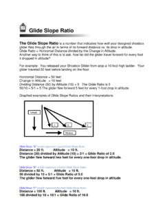
6 Discharge Voltage and Li Plating Works well when large amounts of active Li are plated Difficult to see small amounts, cannot see isolated Li 11. Plated Li Goes Away with Time Some is absorbed into the carbon anode Some becomes separated from the anode and waits in the separator Discharge of Cell with 8-10% plated Li 12. Over Potential vs. SOC and Temperature Look for added anode over potential at low temperature and high charge rate Over potential is charge voltage minus reversible potential Plating started after about volt over potential increase 13. Resistance vs. SOC and Temperature Look for added anode resistance at low temperature and high charge rate Resistance is the slope of the I/V. curve for the cell during recharge 14. Mapping the Safe Charging Region for a Cell Each cell design has a critical voltage threshold at each charge current and temperature, such that charging above that threshold will cause Li Plating 15.
7 Electrolyte Polarization to Detect Localized Plating Measure slow (over ~10-15 minutes) relaxation component of cell voltage Resistance is the slow voltage relaxation divided by a small current change that caused the relaxation 50% DOD life test at 10 C, 8 cycles per day*. *Cell B failed after 1400 cycles due to capacity loss, Cell A had little capacity loss 16. Calorimetry*. Extra heat generation seen after high rate recharge to deposit Li metal Note decrease in heat over time * A. H. Zimmerman and M. V. Quinzio, Thermal Behavior of Large Lithium -Ion Cells , 2004 NASA Battery Workshop, November 2004. 17. Conclusions Many reasons for Li Plating Cell design factors Cell operating environment (low temperature). Charge rate Non-uniformities within stack No single method can detect Li Plating from all mechanisms Five methods identified as capable of detecting Li Plating Discharge voltage behavior Charge voltage over potential Cell resistance changes during recharge Unusual changes in cell electrolyte polarization Calorimetric detection of anomalous heat that decreases with time 18.
8 Acknowledgement The Aerospace Corporation (Aerospace) is gratefully acknowledged for supporting this work as part of the Aerospace Independent Research and Development Program. 19.