Transcription of LM1036 Dual DC Operated Tone/Volume/Balance …
1 JAN1995 REVISEDAPRIL2013LM1036 DualDCOperatedTone/ volume /BalanceCircuit CheckforSamples:LM10361 FEATURESDESCRIPTIONTheLM1036isa DCcontrolledtone(bass/treble),2 WideSupplyVoltageRange,9 Vto16 Vvolumeandbalancecircuitforstereoapplica tionsin LargeVolumeControlRange,75dBTypicalcarra dio, ToneControl, 15dBTypicalcontrolinputallowsloudnesscom pensationtobesimplyeffected. ChannelSeparation,75dBTypical LowDistortion, ,treble, , HighSignaltoNoise,80dBTypicalforanaltern atively, zenerregulatedsupplyprovidedonthe ,standardwarranty,andusein 1995 2013, JAN1995 (1)(2)SupplyVoltage16 VControlPinVoltage(Pins4,7,9,12,14)VCCO peratingTemperatureRange0 C to+70 CStorageTemperatureRange 65 C to+150 CPowerDissipation1 WLeadTemp.(Soldering,10seconds)260 C(1) functional,butdonotensurespecificperform ancelimits.(2)If Military/Aerospacespecifieddevicesarereq uired, (1)VCC=12V,TA=25 C (unlessotherwisestated) ,13;f=1kHzVCC=9V, ,19;f=1kHz, 10dBInputResistancePins2,19;f=1kHz2030k OutputResistancePins8,13;f=1kHz20 MaximumGainV(Pin12)=V(Pin17);f=1kHz 202dBVolumeControlRangef=1kHz7075dBGainT rackingf=1kHzChannel1 Channel20 dBthrough 40dB13dB 40dBthrough 60dB2dBBalanceControlRangePins8,13;f=1kH z1dB 26 20dBBassControlRange(2)f=40Hz,Cb= FV(Pin14)=V(Pin17)121518dBV(Pin14)=0V 12 15 18dBTrebleControlRange(2)f=16kHz,Ct,= FV(Pin4)=V(Pin17)121518dBV(Pin4)=0V 12 15 18dBTotalHarmonicDistortionf=1kHz,VIN= ,MaximumGain6075dB(1)Themaximumpermissib leinputlevelis (2)Thetonecontrolrangeis definedbycapacitorsCbandCt.
2 1995 2013, JAN1995 REVISEDAPRIL2013 ElectricalCharacteristics(1)(continued)V CC=12V,TA=25 C (unlessotherwisestated)ParameterConditio nsMinTypMaxUnitsSignal/NoiseRatioUnweigh ted100Hz 20kHz80dBMaximumGain,0 dB= (3)Gain=0dB,VIN= 20dB,VIN= (3)1016 VSupplyRippleRejection200mVrms,1 kHzRipple3550dBControlInputCurrentsPins4 ,7,9,12,14(V=0V) AFrequencyResponse 1 dB(FlatResponse250kHz20Hz 16kHz)(3)Gaussiannoise,measuredovera periodof50msperchannel,witha CCIR filterreferencedto2 1995 2013,TexasInstrumentsIncorporatedSubmitD ocumentationFeedback3 ProductFolderLinks:LM1036LM1036 SNAS525C JAN1995 (GainvsFrequency) (GainvsFrequency) 1995 2013, JAN1995 REVISEDAPRIL2013 TypicalPerformanceCharacteristics(contin ued) 1995 2013,TexasInstrumentsIncorporatedSubmitD ocumentationFeedback5 ProductFolderLinks:LM1036LM1036 SNAS525C JAN1995 (treble)andCb(bass).Thetoneresponsesared efinedbytherelationships:where ab=at=0formaximumbassandtrebleboostrespe ctively ab=at=1formaximumcut(1) F F asshownintheApplicationCircuit, zenervoltage(pin17= )is DClevelofonehalfofthezenervoltageontheco ntrolinputs,pins4,9,and14,resultsin thisis thecase, simpleloudnesscompensationmaybeeffectedb yapplyinga Thereisnoloudnesscompensationwhenpin7 canbeconnectedtopin12togivetheloudnessco mpensatedvolumecharacteristicasillustrat edwithouttheadditionoffurtherexternalcom ponents.
3 (Tonesettingsareforflatresponse,CbandCta sgiveninApplicationCircuit.)Modification totheloudnesscharacteristicispossiblebyc hangingthecapacitorsCbandCtfora differentbasicresponseor,bya resistornetworkbetweenpins7 and12fora carriedoutintwostages,controlledbytheDCv oltageonpin12,toimprovesignalhandlingcap abilityandprovidea beforethetonecontrolprocessingandprovide saninitial15dBofgainreduction,soensuring thatthetonesectionsarenotoverdrivenbylar geinputlevelswhenoperatingwitha Vrms,VCC=12V( ,VCC=9V).Atreducedgain(< 6 dB)theinputstagewilloverloadif ,VCC=12V( ,VCC=9V).Asthereis volumecontrolontheinputstages,theinputsm aybeoperatedwitha loweroverloadmarginthanwouldotherwisebea cceptable,allowinga possibleimprovementin 1995 2013, JAN1995 REVISEDAPRIL2013 ApplicationCircuitCopyright 1995 2013,TexasInstrumentsIncorporatedSubmitD ocumentationFeedback7 ProductFolderLinks:LM1036LM1036 SNAS525C JAN1995 dualDCcontrolledbass,treble, , , thedatasheet,basicallyforanincreasein thetreblecontrolrangeCtmustbeincreased, thestandardapplicationcircuit.
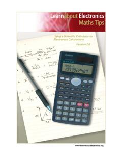
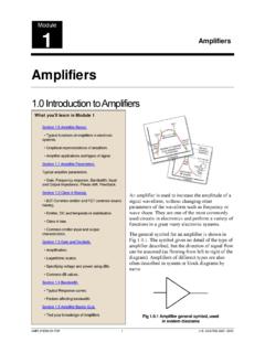
4 (Ct= F,Cb= F). (GainvsFrequency)Figure15andFigure16show theeffectofchangingtheresponsedefiningca pacitorsCtandCbto2Ct,Cb/2and4Ct, Cb/4respectively, (GainvsFrequency)8 SubmitDocumentationFeedbackCopyright 1995 2013, JAN1995 (GainvsFrequency)Figure17showstheeffecto fchangingCtandCbintheoppositedirectionto Ct/2, it isrequiredtogivea particularemphasisto,forexample, ,Ctisillustratedin resistorinserieswithCt. Thetrebleboostandcutwillbe3 dBlessthanthestandardcircuitwhenR= similareffectmaybeobtainedforthebassresp onsebyreducingthevalueoftheACbypasscapac itorsonpins5 (channel1)and16(channel2).Theinternalres istanceatthesepinsis andthebassboost/cutwillbeapproximately3 willbeseenfromFigure15andFigure16thatmod ifyingCtandCbforgreatercontrolrangealsoh astheeffectofflatteningthetonecontrolext remesandthismaybeutilized,withorwithouta dditionalmodificationasoutlinedabove, ,thenegative-goingpeaksoftheoutputamplif iersmaybedetectedbelowa certainlevel,andusedtobiasbackthebasscon trolfroma highboostcondition, achievedthroughcontrolofthetonesectionsb ythevoltageappliedtopin7;therefore, normally1 dBmorebassthantrebleboost(40Hz 16kHz) a greaterdifferenceisdesired,it thestandardapplicationcircuitatvariousvo lumelevels(Cb= F).
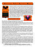
5 Copyright 1995 2013,TexasInstrumentsIncorporatedSubmitD ocumentationFeedback9 ProductFolderLinks:LM1036LM1036 SNAS525C JAN1995 (GainvsFrequency) (GainvsFrequency) (GainvsFrequency) , (loudness)and12( volume )directlyconnected ,loudnesscontrolstartsattypically 8 dBvolume,withmostofthecontrolactioncompl eteby towardsthecontrolreferencevoltage(pin17) .Becausethecontrolinputsarehighimpedance , is possibletoreducetherateofonsetofcontrolt oextendtheactiverangeto , Witha suitablelevelshiftingnetworkbetweenpins1 2and7, 1995 2013, JAN1995 theusualapplicationcircuit, it is required,someadditionalboostcanbeobtaine dbyrestrictingthetonecontrolrangeandmodi fyingCt, Cb, circuitillustratingthisforthecaseofbassb oostisshowninFigure26. 1995 2013,TexasInstrumentsIncorporatedSubmitD ocumentationFeedback11 ProductFolderLinks:LM1036LM1036 SNAS525C JAN1995 basicresponsetypically1 dBdownat250kHz(tonecontrolsflat)andthere forebyscalingCbandCt, it ispossibletoarrangeforoperationovera F andCt= (GainvsFrequency)Characteristic12 SubmitDocumentationFeedbackCopyright 1995 2013, JAN1995 REVISEDAPRIL2013 SimplifiedSchematicDiagram(OneChannel)*C onnectionsreversedCopyright 1995 2013,TexasInstrumentsIncorporatedSubmitD ocumentationFeedback13 ProductFolderLinks:LM1036LM1036 SNAS525C JAN1995 (April2013)toRevisionCPage 1995 2013,TexasInstrumentsIncorporatedProduct FolderLinks.
6 LM1036 PACKAGE OPTION 1 PACKAGING INFORMATIONO rderable DeviceStatus(1)Package TypePackageDrawingPinsPackageQtyEco Plan(2)Lead/Ball Finish(6)MSL Peak Temp(3)Op Temp ( C)Device Marking(4/5)SamplesLM1036M/NOPBLIFEBUYSO ICDW2036 Green (RoHS& no Sb/Br)CU SNLevel-3-260C-168 HR0 to 70LM1036 MLM1036MX/NOPBLIFEBUYSOICDW201000 Green (RoHS& no Sb/Br)CU SNLevel-3-260C-168 HR0 to 70LM1036 MLM1036N/NOPBLIFEBUYPDIPNFH2018 Green (RoHS& no Sb/Br)CU SNLevel-1-NA-UNLIM0 to 70LM1036N (1) The marketing status values are defined as follows:ACTIVE: Product device recommended for new : TI has announced that the device will be discontinued, and a lifetime-buy period is in : Not recommended for new designs. Device is in production to support existing customers, but TI does not recommend using this part in a new : Device has been announced but is not in production. Samples may or may not be : TI has discontinued the production of the device. (2) Eco Plan - The planned eco-friendly classification: Pb-Free (RoHS), Pb-Free (RoHS Exempt), or Green (RoHS & no Sb/Br) - please check for the latest availabilityinformation and additional product content : The Pb-Free/Green conversion plan has not been (RoHS): TI's terms "Lead-Free" or "Pb-Free" mean semiconductor products that are compatible with the current RoHS requirements for all 6 substances, including the requirement thatlead not exceed by weight in homogeneous materials.
7 Where designed to be soldered at high temperatures, TI Pb-Free products are suitable for use in specified lead-free (RoHS Exempt): This component has a RoHS exemption for either 1) lead-based flip-chip solder bumps used between the die and package, or 2) lead-based die adhesive used betweenthe die and leadframe. The component is otherwise considered Pb-Free (RoHS compatible) as defined (RoHS & no Sb/Br): TI defines "Green" to mean Pb-Free (RoHS compatible), and free of Bromine (Br) and Antimony (Sb) based flame retardants (Br or Sb do not exceed by weightin homogeneous material) (3) MSL, Peak Temp. - The Moisture Sensitivity Level rating according to the JEDEC industry standard classifications, and peak solder temperature. (4) There may be additional marking, which relates to the logo, the lot trace code information, or the environmental category on the device. (5) Multiple Device Markings will be inside parentheses.
8 Only one Device Marking contained in parentheses and separated by a "~" will appear on a device. If a line is indented then it is a continuationof the previous line and the two combined represent the entire Device Marking for that device. (6) Lead/Ball Finish - Orderable Devices may have multiple material finish options. Finish options are separated by a vertical ruled line. Lead/Ball Finish values may wrap to two lines if the finishvalue exceeds the maximum column width. Important Information and Disclaimer:The information provided on this page represents TI's knowledge and belief as of the date that it is provided. TI bases its knowledge and belief on informationprovided by third parties, and makes no representation or warranty as to the accuracy of such information. Efforts are underway to better integrate information from third parties. TI has taken andPACKAGE OPTION 2continues to take reasonable steps to provide representative and accurate information but may not have conducted destructive testing or chemical analysis on incoming materials and and TI suppliers consider certain information to be proprietary, and thus CAS numbers and other limited information may not be available for release.
9 In no event shall TI's liability arising out of such information exceed the total purchase price of the TI part(s) at issue in this document sold by TI to Customer on an annual basis. TAPE AND REEL INFORMATION*All dimensions are nominalDevicePackageTypePackageDrawingPi nsSPQReelDiameter(mm)ReelWidthW1 (mm)A0(mm)B0(mm)K0(mm)P1(mm)W(mm)Pin1 QuadrantLM1036 MATERIALS Materials-Page 1*All dimensions are nominalDevicePackage TypePackage DrawingPinsSPQL ength (mm)Width (mm)Height (mm) LM1036 MATERIALS Materials-Page 2 MECHANICAL (Rev G) OUTLINEC MAX18X 05/2016 SOIC - mm max heightDW0020 ASOICNOTES: 1. All linear dimensions are in millimeters. Dimensions in parenthesis are for reference only. Dimensioning and tolerancing per ASME 2. This drawing is subject to change without notice. 3. This dimension does not include mold flash, protrusions, or gate burrs. Mold flash, protrusions, or gate burrs shall not exceed mm per side.
10 4. This dimension does not include interlead flash. Interlead flash shall not exceed mm per Reference JEDEC registration MS-013. 1 IDAREANOTE 4 SEATING SEE DETAIL ADETAIL ATYPICALSCALE BOARD LAYOUT( ) MAXALL MINALL AROUND20X (2)20X ( )18X ( )(R) 05/2016 SOIC - mm max heightDW0020 ASOICSYMMSYMMLAND PATTERN EXAMPLESCALE:6X1101120 notes : (continued) 6. Publication IPC-7351 may have alternate designs. 7. Solder mask tolerances between and around signal pads can vary based on board fabrication site. METALSOLDER MASKOPENINGNON SOLDER MASKDEFINEDSOLDER MASK DETAILSSOLDER MASKOPENINGMETAL UNDERSOLDER MASKSOLDER STENCIL DESIGN( )18X ( )20X ( )20X (2)4220724/A 05/2016 SOIC - mm max heightDW0020 ASOICNOTES: (continued) 8. Laser cutting apertures with trapezoidal walls and rounded corners may offer better paste release. IPC-7525 may have alternate design recommendations. 9. Board assembly site may have different recommendations for stencil design.