Transcription of LM340/LM78XX Series 3-Terminal Positive Regulators
1 LM340/LM78XX Series3-Terminal Positive RegulatorsGeneral DescriptionThe LM140/LM340A/LM340/LM7800C monolithic 3-terminalpositive voltage Regulators employ internal current-limiting,thermal shutdown and safe-area compensation, makingthem essentially indestructible. If adequate heat sinking isprovided, they can deliver over output current. They areintended as fixed voltage Regulators in a wide range ofapplications including local (on-card) regulation for elimina-tion of noise and distribution problems associated withsingle-point regulation. In addition to use as fixed voltageregulators, these devices can be used with external compo-nents to obtain adjustable output voltages and effort was expended to make the entire seriesof Regulators easy to use and minimize the number of exter-nal components. It is not necessary to bypass the output,although this does improve transient response.
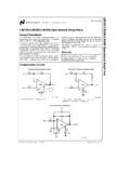
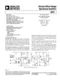
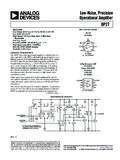
2 Input by-passing is needed only if the regulator is located far from thefilter capacitor of the power 5V, 12V, and 15V regulator options are available in thesteel TO-3 power package. The LM340A/LM340/LM7800 Cseries is available in the TO-220 plastic power package, andthe is available in the SOT-223 package, as wellas the and LM340-12 in the surface-mountTO-263 specifications at 1A loadnOutput voltage tolerances of 2% at Tj= 25 C and 4%over the temperature range (LM340A)nLine regulation of of VOUT/V of VINat 1A load(LM340A)nLoad regulation of of VOUT/A (LM340A)nInternal thermal overload protectionnInternal short-circuit current limitnOutput transistor safe area protectionnP+Product Enhancement testedDeviceOutputVoltagesPackagesLM1405 , 12, 15 TO-3 (K)LM340A/LM340 5, 12, 15 TO-3 (K), TO-220 (T),SOT-223 (MP), TO-263 (S)(5V and 12V only)LM7800C5, 8, 12,15TO-220 (T)Typical ApplicationsFixed Output RegulatorAdjustable Output Regulator00778101*Required if the regulator is located far from the power supply filter.
3 **Although no output capacitor is needed for stability, it does help transientresponse. (If needed, use F, ceramic disc).00778102 VOUT= 5V + (5V/R1 + IQ) R2 5V/R1>3IQ,load regulation (Lr) [(R1 + R2)/R1] (Lrof LM340-5).Current RegulatorComparison between SOT-223 and D-Pak (TO-252)Packages00778103 IQ= mA over line and load 1:1 November 2002LM340/LM78XX Series 3-Terminal Positive Regulators 2002 National Semiconductor Corporation Maximum Ratings(Note 1)If Military/Aerospace specified devices are required,please contact the National Semiconductor Sales Office/Distributors for availability and specifications.(Note 5)DC Input VoltageAll Devices exceptLM7824/LM7824C35 VLM7824/LM7824C40 VInternal Power Dissipation (Note 2)Internally LimitedMaximum Junction Temperature150 CStorage Temperature Range 65 C to +150 CLead Temperature (Soldering, 10 sec.)TO-3 Package (K)300 CTO-220 Package (T), TO-263 Package (S)230 CESD Susceptibility (Note 3)2 kVOperating Conditions(Note 1)Temperature Range (TA) (Note 2)LM140A, LM140 55 C to +125 CLM340A, LM340, LM7805C,LM7812C, LM7815C, LM7808C0 C to +125 CLM340A Electrical CharacteristicsIOUT= 1A, 55 C TJ +150 C (LM140A), or 0 C TJ + 125 C (LM340A) unless otherwise specified (Note 4)Output Voltage5V12V15 VSymbolInput Voltage (unless otherwise noted)10V19V23 VUnitsParameterConditionsMin Typ Max Min Typ Max Min Typ MaxVOOutput Voltage TJ= 25 5 12 15 VPD 15W, 5 mA IO VVMIN VIN VMAX( VIN 20) ( VIN 27) ( VIN 30) V VOLine Regulation IO= 500 mA101822 mV VIN( VIN 20) ( VIN 27) ( VIN 30) VTJ= 25 C3 104 184 22 mV VIN( VIN 20) ( VIN 27) ( VIN 30) VTJ= 25 C4910 mVOver Temperature123030 mV VIN(8 VIN 12)
4 (16 VIN 22) (20 VIN 26)V VOLoad Regulation TJ= 25 C 5 mA IO 2512 3212 35 mV250 mA IO 750mA151921 mVOver Temperature,256075 mV5mA IO 1 AIQQ uiescentCurrentTJ= 25 C666 mAOver mA IQQuiescentCurrent5mA IO 25 C, IO= mAVMIN VIN VMAX( VIN 20) ( VIN 27) ( VIN 30) VIO= 500 mAVMIN VIN VMAX(8 VIN 25) (15 VIN 30) ( VIN 30) VVNO utput NoiseVoltageTA= 25 C, 10 Hz f 100 kHz407590 VRipple Rejection TJ= 25 C, f = 120 Hz, IO=1A688061726070dBor f = 120 Hz, IO= 500 mA,686160dBOver Temperature,VMIN VIN VMAX(8 VIN 18) (15 VIN 25)( VIN )VROD ropout Voltage TJ= 25 C, IO= Electrical Characteristics(Continued)IOUT= 1A, 55 C TJ +150 C (LM140A), or 0 C TJ + 125 C (LM340A) unless otherwise specified (Note 4)Output Voltage5V12V15 VSymbolInput Voltage (unless otherwise noted)10V19V23 VUnitsParameterConditionsMin Typ Max Min Typ Max Min Typ MaxOutputResistancef=1kHz81819m Short-CircuitCurrentTJ= 25 OutputCurrentTJ= 25 TC ofVOMin, TJ= 0 C, IO= 5 mA CVINI nput VoltageTJ= 25 CRequired RegulationLM140 Electrical Characteristics(Note 4) 55 C TJ +150 C unless otherwise specifiedOutput Voltage5V12V15 VSymbolInput Voltage (unless otherwise noted)10V19V23 VUnitsParameterConditionsMin Typ Max Min Typ Max Min Typ MaxVOOutput VoltageTJ= 25 C, 5 mA IO 5 12 15 VPD 15W, 5 mA IO VVMIN VIN VMAX(8 VIN 20) ( VIN 27) ( VIN 30)V VOLine RegulationIO= 500 mA TJ= 25 C3 504 1204 150 mV VIN(7 VIN 25) ( VIN 30) ( VIN 30)V 55 C TJ +150 C50120150 mV VIN(8 VIN 20) (15 VIN 27)( VIN 30)VIO 1 ATJ= 25 C50120150 mV VIN( VIN 20) ( VIN 27) ( VIN 30)V 55 C TJ +150 C256075 mV VIN(8 VIN 12)
5 (16 VIN 22) (20 VIN 26) V VOLoad Regulation TJ= 25 C 5 mA IO 5012 12012 150 mV250 mA IP 750mA256075 mV 55 C TJ +150 C,50120150 mV5mA IO 1 AIQQ uiescent Current IO 1 ATJ= 25 C666 mA 55 C TJ +150 C777 mA IQQuiescent Current 5 mA IO 25 C, IO mAVMIN VIN VMAX(8 VIN 20) (15 VIN 27)( VIN 30)VIO= 500 mA, 55 C TJ +150 mAVMIN VIN VMAX(8 VIN 25) (15 VIN 30)( VIN 30)VLM340 Electrical Characteristics(Note 4) (Continued) 55 C TJ +150 C unless otherwise specifiedOutput Voltage5V12V15 VSymbolInput Voltage (unless otherwise noted)10V19V23 VUnitsParameterConditionsMin Typ Max Min Typ Max Min Typ MaxVNOutput NoiseVoltageTA= 25 C, 10 Hz f 100 kHz407590 VRipple RejectionIO 1A, TJ= 25 Cor68 8061 7260 70dBf = 120 HzIO 500 mA,686160dB 55 C TJ +150 CVMIN VIN VMAX(8 VIN 18) (15 VIN 25)( VIN )VROD ropout Voltage TJ= 25 C, IO= Resistance f = 1 kHz81819m Short-CircuitCurrentTJ= 25 OutputCurrentTJ= 25 TC ofVOUT0 C TJ +150 C, IO= 5 mA CVINI nput VoltageTJ= 25 C, IO 1 ARequired RegulationLM340/LM7800C Electrical Characteristics(Note 4)0 C TJ +125 C unless otherwise specifiedOutput Voltage5V12V15 VSymbolInput Voltage (unless otherwise noted)10V19V23 VUnitsParameterConditionsMin Typ Max Min Typ Max Min Typ MaxVOOutput VoltageTJ= 25 C, 5 mA IO 5 12 15 VPD 15W, 5 mA IO VVMIN VIN VMAX( VIN 20) ( VIN 27)( VIN 30) V VOLine RegulationIO= 500 mA TJ= 25 C3 504 1204 150 mV VIN(7 VIN 25) ( VIN 30)( VIN 30) V0 C TJ +125 C50120150 mV VIN(8 VIN 20) (15 VIN 27) ( VIN 30) VIO 1 ATJ= 25 C50120150 mV VIN( VIN 20) ( VIN 27)( VIN 30) V0 C TJ +125 C256075 mV VIN(8 VIN 12) (16 VIN 22)
6 (20 VIN 26) V VOLoad RegulationTJ= 25 C 5 mA IO 5012 12012 150 mV250 mA IO 750 mA256075 mV5mA IO 1A, 0 C TJ +125 C50120150 mVIQQ uiescent Current IO 1 ATJ= 25 C888 mA0 C TJ +125 mA IQQuiescent Current 5 mA IO Electrical Characteristics(Note 4) (Continued)0 C TJ +125 C unless otherwise specifiedOutput Voltage5V12V15 VSymbolInput Voltage (unless otherwise noted)10V19V23 VUnitsParameterConditionsMin Typ Max Min Typ Max Min Typ MaxChangeTJ= 25 C, IO mAVMIN VIN VMAX( VIN 20) ( VIN 27)( VIN 30) VIO 500 mA, 0 C TJ +125 mAVMIN VIN VMAX(7 VIN 25) ( VIN 30)( VIN 30) VVNO utput NoiseVoltageTA= 25 C, 10 Hz f 100 kHz407590 VRipple RejectionIO 1A, TJ=25 C62 8055 7254 70dBf = 120 Hzor IO 500 mA, 625554dB0 C TJ +125 CVMIN VIN VMAX(8 VIN 18) (15 VIN 25) ( VIN )VROD ropout VoltageTJ= 25 C, IO= Resistance f = 1 kHz81819m Short-Circuit Current TJ= 25 OutputCurrentTJ= 25 TC of VOUT0 C TJ +125 C, IO= 5 mA CVINI nput VoltageTJ= 25 C, IO 1 ARequired RegulationNote 1:Absolute Maximum Ratings are limits beyond which damage to the device may occur.
7 Operating Conditions are conditions under which the device functionsbut the specifications might not be guaranteed. For guaranteed specifications and test conditions see the Electrical 2:The maximum allowable power dissipation at any ambient temperature is a function of the maximum junction temperature for operation (TJMAX= 125 Cor 150 C), the junction-to-ambient thermal resistance ( JA), and the ambient temperature (TA). PDMAX=(TJMAX TA)/ JA. If this dissipation is exceeded, the dietemperature will rise above TJMAXand the electrical specifications do not apply. If the die temperature rises above 150 C, the device will go into thermal the TO-3 package (K, KC), the junction-to-ambient thermal resistance ( JA) is 39 C/W. When using a heatsink, JAis the sum of the 4 C/W junction-to-casethermal resistance ( JC) of the TO-3 package and the case-to-ambient thermal resistance of the heatsink.
8 For the TO-220 package (T), JAis 54 C/W and JCis4 C/W. If SOT-223 is used, the junction-to-ambient thermal resistance is 174 C/W and can be reduced by a heatsink (see Applications Hints on heatsinking).If the TO-263 package is used, the thermal resistance can be reduced by increasing the PC board copper area thermally connected to the package: Using squareinches of copper area, JAis 50 C/W; with 1 square inch of copper area, JAis 37 C/W; and with or more inches of copper area, JAis 32 3:ESD rating is based on the human body model, 100 pF discharged through k .Note 4:All characteristics are measured with a F capacitor from input to ground and a F capacitor from output to ground. All characteristics exceptnoisevoltage and ripple rejection ratio are measured using pulse techniques (tw 10 ms, duty cycle 5%). Output voltage changes due to changes in internal temperaturemust be taken into account 5:A military RETS specification is available on request.
9 At the time of printing, the military RETS specifications for the , LM140AK-12/883,and LM140AK-15/883 complied with the min and max limits for the respective versions of the LM140A. At the time of printing, the military RETS specifications forthe , LM140K-12/883, and LM140K-15/883 complied with the min and max limits for the respective versions of the LM140. The LM140H/883,LM140K/883, and LM140AK/883 may also be procured as a Standard Military Characteristics0 C TJ +150 C, VI= 14V, IO= 500 mA, CI= F, CO= F, unless otherwise specifiedSymbolParameterConditions(Note 6)LM7808 CUnitsMin Typ MaxVOOutput VoltageTJ= 25 VOLine RegulationTJ= 25 VI 160 VI VOLoad RegulationTJ= 25 mA IO 160 mV250 mA IO VI 23V, mA IO , P CurrentTJ= 25 IQQuiescentWith Line VI ChangeWith Load mA IO 25 C, 10 Hz f 100 kHz52 V VI/ VORipple Rejectionf = 120 Hz, IO= 350 mA, TJ= 25 C5672dBVDOD ropout VoltageIO= , TJ= 25 Resistancef = kHz16m IOSO utput Short Circuit CurrentTJ= 25 C, VI= Output CurrentTJ= 25 VO/ T Average TemperatureIO= CCoefficient of Output VoltageNote 6.
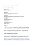
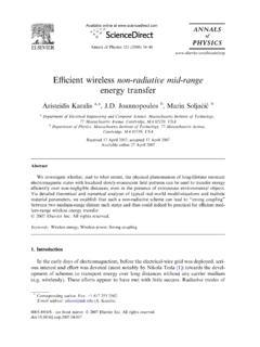
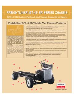
10 All characteristics are measured with a F capacitor from input to ground and a F capacitor from output to ground. All characteristics exceptnoisevoltage and ripple rejection ratio are measured using pulse techniques (tw 10 ms, duty cycle 5%). Output voltage changes due to changes in internal temperaturemust be taken into account Performance CharacteristicsMaximum Average Power DissipationMaximum Average Power Dissipation0077812200778123 Maximum Power Dissipation (TO-263)(See Note 2)Output Voltage (Normalized to 1V at TJ= 25 C)0077812400778125 Note:Shaded area refers to LM340A/LM340, LM7805C, LM7812C RejectionRipple Rejection0077812600778127LM340 Performance Characteristics(Continued)Output ImpedanceDropout Characteristics0077812800778129 Quiescent CurrentPeak Output Current00778130 Note:Shaded area refers to LM340A/LM340, LM7805C, LM7812C VoltageQuiescent Current00778132 Note.