Transcription of lnvensys Building Systems VB-7213 Series 1354 Clifford ...
1 lnvensys Building Systems 1354 Clifford Avenue (Zip 61111) Box 2940 VB-7213 Series nvensys, Loves Park, IL 61132-2940 United States of America l/2 to 2 Screwed NPT Stem Up Open, Two-Way Valves General Instructions Application VB-7213 Series single seat, stem up open, two-way valves control water from 20 to 281 F (-7 to 138 C) or steam to 281 F (138%) maximum in heating or air conditioning are used for two-position or proportional control applications. Valve assemblies require an actuator and a valve linkage. A large selection of factory assembled combinations is available.
2 Consult the Siebe Environmental Controls Catalog, F-25683. n ! Danger: Do not use for combustible gas applications. The VB-7213 Series valve packings are not rated for combustible gas applications, and if used in these applications, gas leaks and explosions could result. Features Valve sizes l/2 to 2 250 psig pressure rating per ANSI Standards ( ) for screwed cast bronze bodies Spring-loaded TFE packing American Standard Taper Pipe Thread (NPT) connections Applicable Literature Siebe Environmental Controls Catalog, F-25683 Siebe Environmental Controls Cross-Reference Guide, F-23638 Siebe Environmental Controls Reference Manual, F-21 683 Siebe Environmental Controls Application Manual, F-2 1335 Control Valve Sizing, F-l 3755 Valve Selection Chart for Steam, F-l 1366 Valve Selection Chart for Water, F-l 1080 EN-205 Water system Guidelines, F-26080 Printed in 9-97 F-26075 SPECIFICATIONS Table-l Specifications/Models.
3 Service Specifications Valve Body Series VB-7213 -O-4-P 1 Chilled or Hot Water and Steam Flow Characteristics (Figure-1) 1 Eaual Percentaae Action I Stem UD ODen Sizes Type of End Fitting Valve Materials Body Seat Stem Plug 112 to 2 NPT Bronze Bronze Stainless Steel Brass Packing 1 Spring-loaded TFE Disc 1 EPDM ANSI Pressure Class (Figure-2) I 250 (up to 400 psig below 1 50 F)a Maximum Inlet Pressure, Steam I35 psig (241 kPa) Allowable Control MediaTemperature 120 to 281 F (-7 to 138 C) Allowable Differential Pressure for Waterb 35 psi (241 kPa) Max.
4 For Normal Life (refer to Cavitation Limitations on Valve Pressure Drop on page 7) Allowable Differential Pressure for Steamb I 20 psi (138 kPa) Valve Size C, Rating kvs RatingC Complete Valve Body Part Number VB-7213 -O-4-1 VB-7213 -O-4-2 l/2 VB-7213 -0-4-3 I I I VB-7213 -0-4-4 VB-7213 -O-4-5 314 VB-7213 -O-4-6 10 VB-7213 -0-4-7 1 IN 14 12 VB-7213 -0-4-8 1 -l/4 20 17 VB-7213 -O-4-9 1 -l/2 28 24 VB-7213 -o-4-10 2 40 35 VB-7213 -o-4-11 a Do not apply above pressure rating to piping system . b Maximum recommended differential pressure in open position.
5 Do not exceed recommended differential pressure (pressure drop) or integrity of parts may be affected. Exceeding maximum recommended differential pressure voids product warranty. c k,, = m3/h (AP = 100 kPa) C,=k,, Close-off Pressure Rating The close-off pressure rating is dependent on the size of the valve, valve linkage, and actuator. Consult the Siebe Environmental Controls Catalog, F-25683, for close-off ratings. 2 Normal Position of Valve Assembly For avalve assembly (valve, linkage, and actuator) to have a normal (spring return) position, the actuator must be of the spring return type.
6 See Table-2 for spring return position of valve assemblies. Table-2 Required Compatible Actuators/Linkages. Actuator Series 1 Required Valve Linkage 1 Normal Position MA-316, MA-416, MA-479 I AV-39 7 I or NC. MA-527 0, MA-521 7, MA-5213 I AV-7600a I Normally Open MC-351, MC-437, MC-437 1, MC5-437 1 1 AV-393 I None MF-547 3, MF-557 3 I AV-7600a I Normally Open MF-22203, MF-22303, MF-22323 MF-63703, MF-63123 Included w/Actuator None MK-2690 I AV-7400 I MK-4601, MK-467 1, MK-4627 MK-6601, MK-6617, MK-6627 AV-407 AV-430 Normally Open MM-400, MMR-400 MM-500, MMR-500 AV-630 or AV-630-010 M P-367 , MP-367, M P-465, M P5-4651 AV-39 1 M P-377 I MP-377, M P-475, M P5-4751 MP-387 I MP-382, MP-387, MP-485, M P-466, MP-4651.
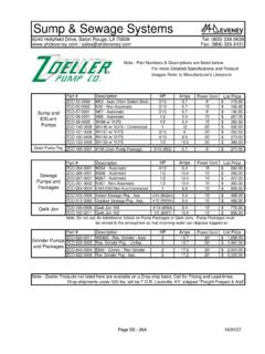
7 M P5-4657 MP-5270, MP-5217, MP-5213 MP-5470, MP-5417 I MP-5413 M P-557 3 MPR-5670, MPR-5671, MPR-5613 MPR-577 3 AV-393 AV-7600a AV-7600 & AV-601 None Normally Open MS-22353 I Included w/Actuator I None High ambient temperatures with high media temperatures in the valve may require the use of AV-601 in addition to AV-7600. See General Instructions for AV-7600 (F-26235) and AV-601 (F-l 9069) for details. Flow Characteristics All valves have modified equal percentage flow characteristics. That is, for equal increments of valve stem stroke, the change in flow rate with respect to valve stroke may be expressed as a constant percent of the flow rate at the time of the change.
8 The change of flow rate with respect to valve stroke is relatively small when the valve plug is near the valve seat and relatively high when the valve plug is nearly wide open. See Figure-l for typical modified equal percentage flow characteristics of VB-7213 Series valve bodies. 60% I $ E 50% / I ,t,/ II Closed Stroke Open Figure-l Typical Modified Equal Percentage Flow Characteristics. 3 Rangeability Rangeability is the ratio of rated flow to the minimum controllable flow through a valve. Table-3 lists the rangeability for VB-7213 Series valves.
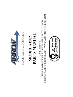
9 Table-3 Rangeability. Valve Body Nominal Part Number Rangeability VB-7213 -0-4-1 51 Valve Body Part Number VB-7213 -O-4-7 Nominal Rangeability 6O:l 1 VB-7213 -0-4-2 1 151 I VB-7213 -O-4-8 1 751 VB-7213 -O-4-3 251 VB-7213 -O-4-9 75:l VB-7213 -O-4-4 4O:l VB-7213 -o-4-10 75:l VB-7213 -O-4-5 5O:l VB-7213 -o-4-11 75:l VB-7213 -O-4-6 6O:l Temperature/Pressure Ratings See Figure-2 for temperature and pressure ratings. Consult the appropriate valve linkage general instruction sheet for the effect of valve body ambient temperatures on specific actuators.
10 Ratings conform with published values and disclaimer. VB-7213 -O-4-P (Screwed Cast Bronze Body) Standards: Pressure to ANSI Class 250 with 400 psig up to 150 F decreasing to 321 psig at 281 F Materials: Bronze, ASTM B584 321 psig (2218 kPa) 6 250(121) e k I 200 (93) !ii iii 150 (65) $ E 100 (38) : Maximum Media Temperature Temperature II I 20 F (-7 C) VB-7213 -0-4-P (it) ~ (Ii:) ~ (lit) ~ (Z&3) ~ 100 200 300 400 (689) (1379) (2068) (2758) Pressure - psig (kPa) Figure-2 Temperature and Pressure Ratings for VB-7213 Series Valve Bodies.