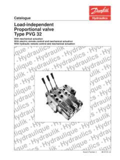
Transcription of Load-independent proportional valve type PVG 32
1 With mechanical actuationWith electric remote control and mechanical actuationWith hydraulic remote control and mechanical actuationBook 8 Partition 2 quennnnHydrauliknnnnHydraulicsnnnnHydrau liquennnnHydrauliknnnnHydraulicsnnnnHydH ydrauliquennnnHydrauliknnnnHydraulicsaul icsnnnnHydrauliquennnnHydrauliknnnnHyHyd raulicsnnnnHydrauliquennnnHydraulikaulik nnnnHydraulicsnnnnHydrauliquennnnHyuliqu ennnnHydrauliknnnnHydraulicsnnnnHydHydra uliquennnnHydrauliknnnnHydraulicliquennn nHydrauliknnnnHydraulicsnnnnHydrlicsnnnn HydrauliquennnnHydraulikliknnnnHydraulic snnnnHydradrauliquennnnHydraudraulicsnnn nHydliqueCatalogueLoad-independentPropor tional valveType pvg 32 valve group4 Plug for external pilot oil supply, PVPC6 PVBS main spools for flow or pressure control7 Electrical LS unloading valve , PVPX7 Technical data8 Electric actuation10 Modules andPump side modules, PVP13code numbersBasic valves, PVB - without LSA/Bpressure limiting valves15 Basic valves, PVB - with LSA/Bpressure limiting valves 16 Mechanical actuator, PVM16 Cover for mechanical actuation, PVMD16 Cover for hydraulic actuation, PVH16 Cover for friction detent, PVMR16 Cover for mechanical float position lock, PVMF16 Electrical actuator, PVE17 Suction valve , PVLA17 Shock and anti-cavitation valve , PVLP18 End plate, PVS, PVSI18 Assembly kit, PVAS18 Electrical LS unloading valve , PVPX18 Plug for external pilot oil supply, PVPC19 Main spools, PVBS19 Technical characteristics22 Dimensions27 Hydraulic systems29 Electrical systems30 System safety31 Other operating conditions34 Module selection chart35 Order specification39 Conversion factors40 The designation G for pipe threads replacesthe previous designation cf.
2 BS/ISO 228 systemPVG 32 is a hydraulic load sensing valvedesigned to give maximum flexibility. From asimple load sensing directional valve , to anadvanced electrically controlled Load-independent proportional pvg 32 module system makes it possibleto build up a valve group to meet compact external dimensions of the valveremain unchanged whatever combination features pvg 32 Load-independent flow control:- Oil flow to an individual function is independent of the load pressure of this function- Oil flow to one function is independent of the load pressure of other functions Good regulation characteristics Energy-saving Up to 10 basic modules per valve group Several types of connection threads Low weightPVG 32 valve groupAccessoriesRemote control units Electrical remote control units- PVRE, PVRET- PVREL- PVRES- Prof 1- Prof 1 CIP Hydraulic remote control unit- PVRHHE lectronics Flow adjustment unit - EHF Ramp generator - EHR Speed control - EHS Closed loop speed control - EHSC Alarm logic - EHA Closed loop position control - EHC PVG CIP CIP Configuration ToolPump side module - PVP Built-in pressure relief valve System pressure up to 300 bar continuous and 320 bar intermittent Pressure gauge connection Versions.
3 - Open centre version for systems with fixeddisplacement pumps- Closed centre version for systems with variable displacement pumps- Pilot oil supply for electrical actuator built into the pump side module- Versions prepared for electrical LS unloading valve PVPXB asic module - PVB Interchangeable spools Depending on requirements the basic module can be supplied with:- Integrated pressure compensator in channel P- Check valve in channel P- Shock/suction valves- LS pressure limiting valves individually adjustable for ports A and B- Different spool variantsActuation modulesThe basic module is always fitted with mecha-nical actuator PVM, which can be combinedwith the following as required: Electrical actuator (12 V or 24 V )- PVES - proportional , super- PVEH - proportional , high performance- PVEM - proportional , medium performance- PVEO - ON/OFF Cover for mechanical actuation, PVMD Cover for mechanical detent, PVMR Cover for mechanical float, PVMF Cover for hydraulic actuation, 32 valve group withopen centre PVP(PVB with flow controlspool) pvg 32 valve group withclosed centre PVP(PVB with flow controlspool)When the pump is started and the main spoolsin the individual basic modules (11) are in theneutral position, oil flows from the pump, through connection P, across the pressure adjustment spool (6) to tank.
4 The oil flow ledacross the pressure adjustment spool determines the pump pressure (stand-by pressure).When one or more of the main spools are actuated, the highest load pressure is fed thro-ugh the shuttle valve circuit (10) to the springchamber behind the pressure adjustment spool (6), and completely or partially closes the connection to pressure is applied to the right-handside of the pressure adjustment spool (6). Thepressure relief valve (1) will open should theload pressure exceed the set value, divertingpump flow back to a pressure-compensated basic module thecompensator (14) maintains a constant pressure drop across the main spool - bothwhen the load changes and when a modulewith a higher load pressure is actuated. With a non pressure-compensated basicmodule incorporating a load drop check valve (18) in channel P, the check valve preventsreturn oil basic module can be supplied without theload drop check valve in channel P for functions with over-centre shock valves PVLP (13) with fixed setting and the suction valves PVLA (17) onports A and B are used for the protection ofthe individual working function against overload and/or adjustable LS pressure limiting valve (12)can be built into the A and B ports of pressure-compensated basic modules to limit the pressure from the individual working LS pressure limiting valves save energycompared with the shock valves PVLP.
5 - With PVLP all the oil flow to the working function will be led across the combined shock and suction valves to tank if the pressure exceeds the fixed With LS pressure limiting valves an oil flow of about 2 l/min will be led across the LS pressure limiting valve to tank if the pressure exceeds the valve the closed centre version an orifice (5) anda plug (7) have been fitted instead of the plug(4). This means that the pressure adjustmentspool (6) will only open to tank when the pressure in channel P exceeds the set valueof the pressure relief valve (1).In load sensing systems the load pressure is led to the pump regulator via the LS connection (8).In the neutral position the pump control setsthe displacement so that leakage in thesystem is compensated for, to maintain the setstand-by pressureWhen a main spool is actuated the pumpregulator will adjust the displacement so thatthe set differential pressure between P and LSis pressure relief valve (1) in PVP should beset at a pressure of approx.
6 30 bar abovemaximum system pressure (set on the pumpor external pressure relief valve ). drawing, PVG1. Pressure relief valve2. Pressure reduction valve for pilot oil supply3. Pressure gauge connection4. Plug, open centre5. Orifice, closed centre6. Pressure adjustment spool7. Plug, closed centre8. LS connection9. LS signal10. Shuttle valvePVPPVBPVB11. Main spool12. LS pressure limiting valve13. Shock and suction valve , PVLP14. Pressure compensator15. LS connection, port A16. LS connection, port B17. Suction valve , PVLA18. Load drop check valve19. Pilot oil supply for PVE20. Max. oil flow adjustment screws for ports A and with check valvePVPC with check valve for open centre PVPPVPC with check valve is used in systems where it is necessaryto operate the pvg 32 valve by means of the electrical remotecontrol without pump flow. When the external solenoid valve isopened, oil from the pressure side of the cylinder is fed via thePVPC through the pressure reducing valve to act as the pilot supply for the electrical actuators.
7 This means that a load can belowered by means of the remote control lever without starting thepump. The built-in check valve prevents the oil from flowing viathe pressure adjustment spool to tank. With the pump functioningnormally the external solenoid valve is closed to ensure that theload is not lowered due to the pilot supply oil flow requirement ofapproximately 1 note:With closed centre PVP the external pilot oil supply can be connected to the pressure gauge connection without the use of aPVPC plug. PVPCPVPC without check valve for open or closed centre PVPPVPC without check valve is used in systems where it is necessary to supply the pvg 32 valve with oil from a manually operated emergency pump without directing oil flow to the pilot oilsupply (oil consumption about 1 l/min).When the main pump is working normally, the oil is directed through the PVPC plug via the pressure reduction valve to the electrical the main pump flow fails, the external shuttle valve ensures that the oil flow from the manually operated emergencypump is used to pilot open the over centre valve and lower the load can only be lowered using the mechanical operating leverof the pvg 32 valve .
8 Plug for external pilot oil supply, PVPCPVPC without check , PVPXPVBS main spools for flowcontrol (standard)In this way the pump pressure will always correspond to the load pressure plus thestand-by pressure of the pressure adjustmentspool or the pump will normally give optimum and stableadjustment of the oil using standard flow control spools, thepump pressure is determined by the highestload pressure. This is done either via the pressure adjustment spool in open centre PVP (fixed displacement pumps) or via the pumpregulator (variable displacement pumps).Due to these factors it is recommended thatpressure control spools are only used when itis known for certain that problems with stabilitywill arise - or already have LS unloadingvalve, PVPXPVBS main spools forpressure controlPVPX is a solenoid LS unloading valve . PVPXis fitted into the pump side module enabling aconnection to be made between the LS andthe tank lines.
9 Thus the LS signal can be relieved to tank by means of an electric a PVP pump side module in open centre version the relief to tank of the LS signal means that the pressure in the system is reduced to the sum of the tank port pressure plus the neutral flow pressure for the pump side a PVP pump side module in closed centreversion the relief to tank of the LS signalmeans that the pressure is reduced to the sumof the tank port pressure for the pump sidemodule plus the stand-by pressure of a few systems load sensing pump pressuremay result in unstable adjustment of the oilflow and a tendency towards system may be the case with working functionsthat have a large moment of inertia or over-centre such systems main spools for pressure con-trol can be spools are designed in such a way thatthe pump pressure is controlled by the spooltravel. The main spool must be displaced untilthe pump pressure just exceeds the load pres-sure before the working function is applied.
10 Ifthe main spool is held in this position, thepump pressure will remain constant - even ifthe load pressure changes - giving a stable use of pressure control spools, however,also means that- the oil flow is load dependent- the dead band is load dependent- the pump pressure can exceed the load pressure by more than is standard control lever 19,5 Regulation range, proportional range 13,4 float position control leverFloat position22,3 Neutral-Max. spoolpositiontravelOperating forcePVM + PVMD2,2 0,3 daN 2,8 0,3 daNPVM + PVE 1)2,2 0,3 daN 2,8 0,3 daNPVM + PVH2,7 0,3 daN 8,3 0,3 daNControl lever positions, see page 6continuous300 bar 2)Port Pintermittent 1)320 bar 2)Max pressurePort A/B350 barPort T, static/dynamic25 bar/40 barPort P140 l/min 4)Oil flow, ratedPort A/B, with press. l/min 3)(See characteristics, page 22 - 24)Port A/B , without press. l/minSpool travel, standard 7 mmProportional range 4,8 mmSpool travel, float position spoolFloat position8 mmDead band, flow control spools 1,5 mmMax.


