Transcription of Low - Fujikura
1 11 Fujikura Technical Review, 20071. Introduction Fiber-to-the-home (FTTH) system is becomingwidely used now. Passive Optical Network (PON)system will be commonly selected because of its cost-effectiveness. In the PON system, every subscriber isrequired to install an Optical Network Unit (ONU) athis/her home. Therefore, cost reduction of the ONUis essential. A major portion of the ONU cost comesfrom an optical transceiver, and, therefore, the costreduction of the transceiver is most have developed a novel transceiver and anOptical Sub-Assembly (OSA), the key element of atransceiver, for Gigabit Ethernet-PON1)(GE-PON),which operates at 1 Gbit/s data rate using Ethernettechnology.
2 A newly developed compact and low-costBidirectional Optical Sub-Assembly (BOSA)2), calledmicro-BOSA, can make the transceiver a small formfactor. The design of the transceiver was also opti-mized for the micro-BOSA, reducing its total cost. The development was a joint work betweenFujikura Ltd. and Oki Electric Industry Co., Ltd. Themembers of Oki Electric Industry took charge of theoptical design and internal structure of the micro-BOSA3)under their Silicon microlens technologies4).Optoelectronic Circuits & Systems R & D Center ofFujikura developed packaging and assembling ofmicro-BOSA and designed the optical Outline of the PON systemFigure 1 shows the outline of the PON system thatis one of the FTTH systems.
3 One optical fiber from acentral office is divided by an optical splitter on theway to subscribers. Multiple subscribers can there-Low - Cost Optical Transceiver for PON Using Micro-BOSAK oichiroMasuko1, KenjiNishide2, SusumuNakaya2, TeijiroOri2, OsamuKikuchi3, RyouSekikawa4and DaisukeShimura4A novel micro-Bidirectional Optical Sub-Assembly (BOSA) has been developed in which opti-cal transmitting and receiving functions are incorporated in a single TO-CAN package . A newcompact and cost-effective Passive Optical Network (PON) Optical Network Unit (ONU) trans-ceiver using the micro-BOSA has also been developed.
4 Low-cost feature is achieved with a pas-sive alignment technology and a simplified integrated structure of the micro-BOSA. Both elec-trical and optical characteristics are sufficient to comply with Gigabit Ethernet (GE)-PONONU transceiver specification. In this paper, the structure and characteristics of the transceiverare reported. Drop cableClosure with splittersAerial cableFeeder cable Central officeGE-PON OLTGE-PON OLTGE-PON PON Applied Electronics Technology Department of Optics and ElectronicsLaboratory2 Optoelectronic Circuits & Systems R & D Center 3 Optical Module R & D Department of Optoelectronic Circuits & Systems R &D Center4 Oki Electric Industry Co.
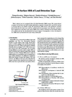
5 , driverBidirectional Optical Sub-Assembly(BOSA)DataBurstsignalDataSig naldetectRx circuit boardPD TO-CANO ptical fiber1,310nm1,490nm1,550nmPost amplifierPre-amplifierPDLDmPDWDMC onventional transceiver for PON ONUTx circuit boardLD Block diagram of an ONU optical share an Optical Line Terminal (OLT) in the cen-tral office. Figure 2 shows the block diagram of a con-ventional GE-PON ONU transceiver. In this system,upstream signal is carried by a 1,310 nm wavelengthlight, and downstream signal is carried by a 1,490 nmwavelength light, so that a bidirectional communica-tion is realized by a single optical fiber.
6 Burst trans-mitting function to operate laser diode (LD) only dur-ing a requested period is also required for the ONUsbecause they share one OLT. The function to shutoff a 1,550 nm signal is alsorequired because a video service on 1,550 nm isplanned in the Structure of the proposed transceiver andthe Conventional transceiverConventional transceiver generally uses a cubicoptical module shown as BOSA in Fig. 3. In this typeof module, a TO-CAN type LD and photodiode (PD)are attached to a cubic body. A Wavelength DivisionMultiplexing (WDM) filter is fixed inside the body soas to make a 45 angle to the LD and PD optical the module itself along with the circuit board ofthe optical transceiver becomes complicated.
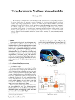
7 A pigtailfiber with an SC connector is usually attached to theBOSA. It results in high material and assemblingcost. Proposed optical transceiverFigure 4 shows the appearance of the proposedoptical transceiver. The transceiver is designed tocomply with the Small Form Factor (SFF)Multisource Agreement (MSA) standard. An SC-typeoptical connector is mated to one end of the transceiv-er. Upstream signal is carried by a 1,310 nm wave-length light, and downstream signal is carried by a1,490 nm wavelength light because the transceiver isdesigned for GE-PON ONU.
8 The transmission datarate is 5 shows the internal structure of the prod-uct. A cylindrical object on the left side is the micro-BOSA and on the right side is a circuit board for theIC with an LD driver and a post amplifier for signalreceiving. Outer shape and internal structure of the micro-BOSAF igure 6 shows a schematic diagram of the micro-BOSA chip. A silicon optical bench (SiOB) with opti-cal devices, called micro-BOSA chip, is fixed in themicro-BOSA. An LD, a PD, Si microlens, a WDM fil-ter, a transimpedance amplifier (TIA), and capacitorsare mounted on the SiOB with passive alignmenttechnologies.
9 Upstream signal from an LD is collimat-ed by an Si microlens, goes through a WDM filter, iscondensed by a ball lens and coupled into an opticalfiber. Downstream signal from the optical fiber is col-limated by the ball lens, reflected by the WDM filter,condensed and bent a little downward by an Si12Tx circuit boardRx circuit boardBOSAO ptical Example of a conventional Outer shape of the proposed optical Internal structure of the proposed optical microlensPre-amplifierWDM filterUp-stream1,310nmDown-stream1,490nm Ball lensSi The micro-BOSA , reflected by a mirror on SiOB and coupledinto a 7 shows the details of the Si microlens thatis a kind of diffractive )
10 The lenses can be fabri-cated in wafer scale based on the conventional Si LSIfabrication technology so that the form can be con-trolled very precisely. An LD coupling efficiency is designed to be 30% forthis micro-BOSA, but a coupling efficiency higherthan 50% can be achieved. The Si microlens can beplaced precisely on a V-groove fabricated by orienta-tion-dependent etching on the SiOB because theouter shape of Si microlens is also precise. The outershape is fabricated using MEMS 8 shows a cut model of the micro-BOSA chip is attached to the ledge of astem.