Transcription of Low Power Folding and Interpolating Analog to Digital ...
1 International Journal of Advance Engineer ing and Research Development (IJAERD). Volume 1,Issue 5,May 2014, e-ISSN: 2348 - 4470 , print-ISSN:2348-6406. Low Power Folding and Interpolating Analog to Digital Converter using 180nm Technology Jayesh L. Prajapati1 , Prof. Priyesh P. Gandhi2. 1. Student, Department of Electronics & Communication Engineering,Laljibhai Chaturbhai Institute of Technology, Bhandu-38412, 2. Asst. Professor, Department of Electronics & Communication Engineering, Laljibhai Chaturbhai Institute of Technology, Bhandu-38412, Abstract Folding and Interpolating A/D converters have been shown to be an effective means of digitization of high bandwidth signals at intermediate resolution.
2 The paper focuses on design of 5-bit Folding & Interpolating ADC. The converter architecture is designed with reduced number of comparators and minimum hardware. The Folding amplifier with Folding factor=4 can be used to produce more than one zero-crossing point to reduce required number of comparators. To achieve the design goal, Folding amplifier is used in the design of coarse and fine converter both. To reduce the Power consumption, encoder based on XOR-OR logic is used. The design is implemented using m technology at voltage. Keywords- Folding amplifier, Interpolation, Comparator, Digital Encoder, Fine ADC, Coarse ADC. I. INTRODUCTION. Analog -to- Digital converters have been incorporated into most of the complex mixed signal systems.
3 However, low-voltage and low- Power constraints often have to be met in these systems, particularly for battery-powered portable devices. Full flash and multi-step flash ADCs are the well-known architectures for a high-speed Analog to Digital conversion [1]. However, these architectures require large Power dissipation. When the need for a relatively high conversion rate and medium resolution dominates, Folding and Interpolating architecture exhibits a good performance. For instance, this architecture has been employed to design a 5-bit Folding and Interpolating ADC using a CMOS technology. The high- speed and low- Power constraints can also be met with Folding and interpolation techniques.
4 However, with this architecture, it is difficult to achieve a high resolution ( , 6-bit) due to the limitation in Folding factor. In this paper a low- Power , four- level folder is designed. This is used to design a low- Power , Folding and interpolation ADC with 5-bit resolution. Thirty two- level Folding signal is achieved by such four Folding amplifier having Folding factor=4. Addition intermediate signals are generated using resistive interpolation technique with interpolation rate=2. After Analog preprocessing, one comparator deals with more quantization levels. Hence, the number of the comparators is reduced. The number of comparators required for a Folding ADC decreases as the Folding order increases.
5 The architecture still keeps high speed conversion feature. Section-II discusses the proposed architecture of Folding and Interpolating ADC. The details of novel low voltage, low Power Folding amplifier is shown in section-III. Section-IV discuses resistive interpolation technique. The high speed low Power comparator and encoder design are described in section-V. Finally, the conclusion is presented in Section V. II. ARCHITECTURE OF Folding & Interpolating ADC. @IJAERD-2014, All rights Reserved 1. International Journal of Advance Engineer ing and Research Development (IJAERD). Volume 1,Issue 5,May 2014, e-ISSN: 2348 - 4470 , print-ISSN:2348-6406. The concept of Folding A/D converter was first introduced by Arbel and Kurz [9] in 1975.
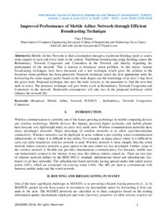
6 The main motivation was the dramatic reduction of the number of comparators required in the design. Fig. 1 shows the block diagram of a Folding A/D converter. The Folding and Interpolating A/D converter contains two separate converters, namely, the coarse and the fine converter. The input signal is fed into both converters in parallel. The input voltage is applied to a pre-processing circuit depicted as the Folding circuit, and the output of this Folding circuit is connected to a N-n-bits fine A/D converter. The input signal is also directly connected to a n-bits coarse A/D converter. Figure 1 Block Diagram of Folding ADC Figure 2 Transfer curve of Folding circuit in comparison with transfer curve of full flash ADC.
7 The operation of the Folding circuit is illustrated in figure 2, where the transfer function of the Folding circuit is given. The input-output characteristics of Folding circuit can be parameterized by number of folds. This parameter determines resolution of both coarse and fine ADC. Lower Folding factors require more fine comparators, while higher Folding factors result in, amongst other things, more pre-processing hardware. The zig- zag shaped transfer curve covers the whole Vin range, and the output voltage of the Folding circuit needs to be converted to only 2N n levels corresponding to the least significant bits (LSB's) of the A/D converter output code. In order to distinguish the n possible input voltages, the n-bit coarse A/D converter is required, which generates the n most significant bits (MSB's) of the A/D converter.
8 The total comparator count for this Folding converter is 2N n (fine) + 2n (coarse), which is much less than the 2N required for a full flash. Also the n most significant bits and the N-n least significant bits are generated synchronously, and thus, a sample and hold function is basically not required. The throughput of a Folding A/D. converter is equal to that of a full- flash, while a two or multi- step converter requires several clock cycles to convert the data. Interpolation further reduces the number of preamplifiers. Due to the Folding characteristic, if the input goes from zero to full scale once, the output goes from Vin to Vmax, F times. The input signal frequency is multiplied in the Analog pre-processing of the A/D converter as a result of the Folding operation.
9 The maximum frequency multiplication in a Folding system is determined by the Folding factor of the A/D converter. A high Folding factor results in fewer comparators, but it lowers the maximum input signal frequency of the A/D converter. The non- linearity errors in the Folding characteristic also depend on the frequency of operation. At high speeds, the rate of the change of the signal becomes comparable with the intrinsic time-constants of the circuit. The input-output characteristic tends to be rounded at the Folding point and hence the non- linearity increases. The non- linearity falls to zero at zero crossing points. Thus, if only these points are considered, the polarity of the difference between input voltage and reference voltage can be determined correctly.
10 An ADC employing Folding technique can produce more zero crossing points than flash ones, thus reducing the number of comparators, Power consumption and chip area. Also the interpolation @IJAERD-2014, All rights Reserved 2. International Journal of Advance Engineer ing and Research Development (IJAERD). Volume 1,Issue 5,May 2014, e-ISSN: 2348 - 4470 , print-ISSN:2348-6406. technique can produce more than one signal thus reducing the number of Folding amplifier and circuit complexity. The LSBs number of zero crossing points is determined by following equation. Z =NF * FF * I .. (1). Where N F is the number of primarily Folding waveform, F F is the Folding factor and I is the interpolation rate.