Transcription of LP SolidStart LSL & LVL Wall Framing Technical Guide
1 Please verify availability with the LP SolidStart Engineered Wood Products distributor in your area prior to specifying these Technical Guide LP SolidStart LSL & LV LWall Framing Technical and LSL and LVL2 IntroductionArchitects are raising the roof and stretching walls beyond the reach of conventional lumber. LP SolidStart LSL and LVL studs redefine the standard for wall Framing by providing structural walls that can be straighter, taller and stronger for both conventional and challenging engineered applications. Because LP manufactures its LSL and LVL to the highest standards, builders know that they ll get fewer callbacks and save themselves time and money. Where traditional lumber studs warp, bow and twist as they dry, LP SolidStart LSL and LVL won t because they start dry from the mill. Having straight walls gives home-owners the peace of mind that their cabinets will stay flush to the wall, their tile and drywall is less likely to crack and their windows and doors will function properly.
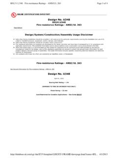
2 That s performance you can count on. Using this Technical Guide , LP SolidStart LSL and LVL can be specified for use in conventional (prescriptive) and engineered wood-frame wall CONSTRUCTION Conventional construction provisions for wood-frame walls are included in the International Building Code (IBC) and the International Residential Code (IRC). In conventional construction, wall members and their connections are selected from tables in the Code rather than being calculated, as in engineered design. LP s compliance with the ICC evaluation Service s Acceptance Criteria for Wood-Based Studs (AC202) permits LP SolidStart LSL and LVL to be a direct substitution to traditional lumber studs prescribed in Section of the IBC and Section R602 of the with AC202 also demonstrates equivalence to the notching provisions prescribed in the Code for traditional lumber studs in conventional construction. FIRE-RESISTIVE WALL CONSTRUCTIONLP SolidStart LSL and LVL ( and higher) are permitted to be used in the 1-hour fire-resistance-rated wall assemblies listed in Table (2) of the IBC, with some additional design and construction considerations as specified in LP s evaluation and product reports.
3 When used in prescriptive wall Framing , LP SolidStart LSL and LVL can be directly substituted for the equivalent size of No 2 or lower grade dimensional lumber. When used in engineered wall construction, some additional limitations are imposed on the load capacity of the studs. For both prescriptive and engineered wall systems, mineral wool insulation is required in the wall cavity. Please refer to ICC- es evaluation report esr -2403 and APA product report PR-L280 for complete information on the use of LP SolidStart LSL and LVL in fire-resistance-rated walls, or use LP s Wood-E Design DESIGN CONSTRUCTIONIn engineered design, calculations based on the expected in-service loads are performed to ensure that the allowable capacities of the wall members are not exceeded. Notches and holes in LP SolidStart LSL and LVL wall Framing are permitted when designed in accordance with the provisions of the National Design Specification for Wood Construction (NDS), with additional adjustments as prescribed herein.
4 The wall stud and exterior wall column tables in this Guide include the effects of notches and holes on their capacity. Refer to Drilling & Notching on page 4 for the limitations of notch and hole size and LIMITSLike floor and roof systems, walls are subject to code-prescribed deflection limits as well as industry recommendations. The IBC prescribes a deflection ratio limit of L/240 for walls with brittle finishes and L/120 for walls with flexible finishes. The IRC prescribes the additional ratio of L/360 for walls with stucco or plaster. Additional deflection limits are recommended for certain windows and wall finishes like brick. Always verify the requirements, but the following table summarizes common deflection LIMITED WARRANTYLP SolidStart Engineered Wood Products are backed by a lifetime limited warranty. Visit or call for a copy of the warranty. A Word About Wall FramingConditionDeflectionFlexible Finish (IBC)L/120 Windows & DoorsL/175 Brittle Finish (IBC)L/240 Plaster & Stucco (IRC)L/360 BrickL/6003 Table of ContentsProduct Specifications, Design Values and Drilling & Notching.
5 4 Wall Stud Capacity (plf) .. 5 Exterior Wall Column Capacity (lbs): 2x4 & 2x6 Walls for 90 mph, Exposure B ..6 Exterior Wall Column Capacity (lbs): 2 x 4 & 2 x 6 Walls for 100 mph, Exposure C .. 7 Exterior Wall Column Capacity (lbs): 2 x 8 Walls for 90 mph, Exposure B .. 8 Exterior Wall Column Capacity (lbs): 2 x 8 Walls for 100 mph, Exposure C ..9 Exterior Wall Column Capacity (lbs): 2 x 10 Walls for 90 mph, Exposure B .. 10 Exterior Wall Column Capacity (lbs): 2 x 10 Walls for 100 mph, Exposure C .. 11 Typical Wall Framing & Wall Stud Example .. 12 Typical Wall Framing : Trimmer & King Stud Examples .. 13 Typical Wall Framing : Wall Column Examples .. 14 Free-Standing Interior Column Capacity (lbs) .. 15 Nailing and Connection Details .. 16-17 Typical Connections .. 18 Handling and Storage Guidelines .. 194 DRILLING & NOTCHINGP roduct Specifications, Design Values and Drilling & NotchingALLOWABLE DESIGN STRESSES (PSI)MaterialGradeBeam (Edgewise) OrientationPlank (Flatwise) OrientationAxialBending Fb3, 4, 6 Modulus of Elasticity MOE9 Shear FvCompression perpendicular-to-grain Fc?
6 Bending Fb5 Modulus of Elasticity MOE9 Shear FvCompression perpendicular-to-grain Fc?Tension Ft7, 8 Compression FcLP SolidStart LSL1730Fb-1 .35E17301 .35 x 10641075019101 .35 x 106155440130016502360Fb-1 .55E23601 .55 x 10641087526201 .55 x 10615544017502175LP SolidStart LVL2250Fb-1 .5E22501 .5 x 10628575022001 .4 x 106140450135023502900Fb-2 .0E29002 .0 x 10628575029502 .0 x 10614055018003200 NOTES:1. LP SolidStart LSL and LVL shall be designed for dry-use conditions only. Dry-use applies to products installed in dry, covered and well ventilated interior conditions in which the equivalent moisture content in lumber will not exceed 16%. Adjustments for high temperature are beyond the scope of this The allowable strengths and stiffness are for normal load duration (10 year). Bending, Shear and Axial Tension and Compression shall be adjusted according to code. Modulus of Elasticity and Compression perpendicular-to-grain shall not be adjusted for load The allowable Bending, Fb, for LP SolidStart LSL in the Beam orientation is tabulated for a standard 12" depth.
7 For depths other than 12," multiply Fb by (12/depth) For depths less than 3-1/2", adjust Fb by The allowable Bending, Fb, for LP SolidStart LVL in the Beam orientation is tabulated for a standard 12" depth. For depths less than 12," multiply Fb by (12/depth) For depths less than 3-1/2," multiply Fb by For depths greater than 12," multiply Fb by (12/depth) The allowable Bending, Fb, in the Plank orientation shall not be adjusted for depth (thickness).6. The allowable edgewise Bending shall also be multiplied by the repetitive member factor, Cr = , when 3 or more pieces are properly connected in direct contact or are used as wall studs spaced no more than 24" oc and properly connected together by an adequate wall The allowable Tension, Ft, for LP SolidStart LSL is assigned for a standard length of 3 feet. For lengths longer than 3 feet, multiply Ft by (3/length) For lengths less than 3 feet, use the design tension stresses in the table above, The allowable Tension, Ft, for LP SolidStart LVL is assigned for a standard length of 3 feet.
8 For lengths longer than 3 feet, multiply Ft by (3/length) For lengths less than 3 feet, use the design tension stresses in the table above, Deflection calculations for LP SolidStart LSL and LVL shall include both bending and shear deformations. Deflection for wall Framing , uniform load: = + Where: = deflection (in) E = modulus of elasticty (from table) w = uniform load (plf) b = width (in) L = design span (ft) d = depth (in direction of bending) (in) Equations for other conditions can be found in engineering CAPACITYStud or Column SizeColumn Bearing (lbs)Stud Bearing (plf)Hem-Fir (405 psi)SPF (425 psi)LP LSL/LVL (440 psi)Concrete (2500 psi)Hem-Fir (405 psi)SPF (425 psi)12" oc16" oc12" oc16" oc1-1/2" x 3-1/2"212522302360446021251590223016701- 1/2" x 5-1/2"334035053710701033402505350526251- 1/2" x 7-1/4"440046204890924044003300462034651- 1/2" x 9-1/4"5615589562401179056154210589544203 -1/2" x 3-1/2"496052055510104103-1/2" x 5-1/2"779581808660163603-1/2" x 7-1/4"102751078011415215653-1/2" x 9-1/4"131101375514565275155-1/4" x 5-1/2"116901227012990245405-1/4" x 7-1/4"154151617517125323505-1/4" x 9-1/4"196652063521850412757" x 5-1/2"155901636017325327257" x 7-1/4"205502156522835431357" x 9-1/4"26220275152913555035 NOTES:1.
9 The capacity for Wood Bearing is based on the compression strength, perpendicular-to-grain, of the bearing plate and shall not be adjusted for load duration. The allowable compression, perpendicular-to-grain, for other species of lumber can be found in the 2012 edition of the National Design Specification for Wood Construction (NDS).2. The Bearing Capacity for concrete is based on a conversion to allowable stress design for comparison to the column capacities in this To determine the Bearing Capacity of a multiple-ply member (such as a double 2 x 4 stud), multiply the Bearing Capacity from the table by the number of plies. The capacity is additive and may be increased for bearing on wood plates per note When a stud or column is located at least 3" from the end of a wall plate, the Bearing Capacities above are permitted to be increased by the bearing area factor, Cb = (Lb + )/Lb, where Lb is the bearing length measured parallel to the grain of the wall plate and is less than 6.
10 " For bearing lengths 6" or more, Cb = :1. Free-standing columns shall not be drilled or notched except as required for proper installation of column caps, bases or other hold-downs without further analysis by a professional engineer. Bolts, lag screws and self-tapping screws shall only be inserted through the face of the column, perpendicular to the face of the strands in LP LSL and the veneers in LP Cutting, notching and boring of nominal 2x4 (1-1/2" x 3-1/2") and 2x6 (1-1/2" x 5-1/2") LP LSL and LP LVL wall studs used in prescriptive wall Framing is permitted in accordance with sections and of the IBC and section of the International Residential Code (IRC).3. For wall applications designed with the tables in this Guide , notching and drilling shall be limited to the restrictions of notes 4 through 6 (see details to left). 4. One hole up to 40% of the stud depth, maximum of 2-3/16," is allowed only in the upper or lower 3 feet or 1/3 of the stud height, h (see Drilling and Notching detail for maximum hole sizes), except do not place a hole within 6" of either end of the stud.