Transcription of LRFD Beam Load Tables - cousesteel.com
1 LRFDBeam load TablesHSSE lectric Resistance Welding (ERW) ProcessIn the tube mill, flat steel strip (1) is formed continuously around itslongitudinal axis to produce a round tube. This is done by moving thestrip through a progressive set of rolls (2-6). The strip edges (7) areheated by either high frequency induction or contact welding and thenforged together by weld rolls to create a continuous longitudinal weldwithout the addition of filler metal. The weld seam (8) is then cooledand processed through a set of sizing/shaping rolls which cold-form itinto a round (9), square (10) or rectangular (11) Weld-Square (ERW) ProcessIn the weld mill, driven forming dies progressively shape the flat strip(1) by forming the top two corners (2) of the square or rectangular tubein the initial forming station. Subsequent stations form the bottom twocorners (3) of the shape. No cold working of the sides of the shape isperformed, and the shape s seam is welded by high-frequency contactswhen the tube is near its final shape and size.
2 The welded tube (4) iscooled and then driven through a series of sizing stations which qualifiesthe tube s final Manufacturing MethodsThe transformation of steel strip into hollow structural sections (HSS) is the result of operations including forming, welding and sizing. Currently threemethods are being used in North America for the manufacture of HSS. These methods, including two ERW methods and an SAW method, are describedbelow. Both ERW methods meet ASTM A 500 and CSA requirements for the manufacture of HSS, and the ERW sizes included in this publicationmay be produced to either standard. The SAW method is not included as a manufacturing process in the ASTM or CSA specification. SAW sizes listed in thispublication can be specified to meet desired physical and dimensional criteria of ASTM A500 and CSA Arc Weld (SAW) ProcessTwo identical pieces of flat strip (1) are placed in a press brake andformed into two identical halves (2) of a finished tube size.
3 A backup baris tack welded to each leg of one of the half-sections (3). The two half-sections are fitted together toe-to-toe (4) and welded by the submergedarc process to complete the square or rectangular section (5).123456789101111223341234521 STI/HSS Member CompaniesOF NORTH AMERICAA tlas Tube, Clark Street, Box 970 Harrow, Ontario N0R 1G0 Telephone: (519) 738-3541(800) 265-6912 Fax: (519) 738-3537 Bull Moose Tube Company1819 Clarkson Road, Suite 100 Chesterfield, MO 63017 Telephone: (636) 537-2600(800) 325-4467 Fax: (636) 537-5848 Eugene Welding Box 249 Marysville, MI 48040 Telephone: (810) 364-7421(800) 336-3926 Fax: (810) 364-4347 Hanna Steel Box 558, Fairfield, AL 35064 Telephone: (205) 780-1111(800) 633-8252 Fax: (205) 783-8296 Hannibal Industries, Box 58814, 3851 Santa Fe Angeles, CA 90058 Telephone: (323) 588-4261 Fax: (323) 589-5640 Independence Tube Corporation6226 W.
4 74th StreetChicago, IL 60638-6196 Telephone: (708) 496-0380(800) 376-6000 Fax: (708) 563-1950 IPSCO Tubulars Box 18, 2011 7th AvenueCamanche, IA 52730 Telephone: (563) 242-0000(800) 950-4772 Fax: (563) 242-9137 LTV Copperweld1855 East 122nd Street Chicago, IL 60633 Telephone: (800) 733-5683 Fax: (773) 646-6128(In Canada)14 Holtby AvenueBrampton, OntarioCanada L6X 2M3 Telephone: (905) 451-2400(800) 268-3005 Fax: (905) 840-4716 Maverick Tube Corporation16401 Swingley Ridge Road,Suite 700 Chesterfield, MO 63017 Telephone: (314) 733-1600(800) 840-8823 Fax: (314) 733-1677 Novamerican Steel Hymus BoulevardDorval, Quebec, Canada H9P 1J8 Telephone: (514) 335-6682(800) 361-1496 Fax: (514) 683-5285(In United States)600 Dean Sievres PlaceMorrisville, PA 19067 Telephone: (215) 295-8813 Fax: (215) 295-8798 Productos Laminados de Monterrey, SA de CVHeadquarters & Monterrey PlantAve. Lazaro Cardenas 1525 Nino ArtilleroMonterrey, Mexico 64280 Telephone: (8) 351-1625(8) 351-1070 Fax: (8) 351-0322( Office)Prolamsa, SW Freeway, Suite 521 Stafford, TX 77477 Telephone: (281) 494-0900 Fax: (281) 494-0990 Valmont Industries (Structural Tube Division) Box 2620 Tulsa, OK 74101 Telephone: (918) 583-5881(800) 331-3002 Fax: (918) 585-1927 Vest, Incorporated6023 Alcoa AvenueLos Angeles, CA 90058 Telephone: (323) 581-8823(800) 421-6370 Fax: (323) 581-3465 Welded Tube of Canada Limited111 Rayette RoadConcord, Ontario,Canada L4K 2E9 Telephone: (905) 669-1111(800) 565-8823 Fax.
5 (905) 738-40704 load and Resistance Factor Design ( lrfd ) beam load Tables are presented for rectangular and square Hollow StructuralSections (HSS) manufactured by the electric resistance welding (ERW) method and the submerged arc welding (SAW) factored uniform loads for simple laterally supported beams have been calculated in accordance with the AISC"Specification for the Design of Steel Hollow Structural Sections April 15, 1997". This Specification is a supplement to theAISC " load and Resistance Factor Design Specification for Structural Steel Buildings December 1, 1993". The factoreduniform loads are based upon section property data for HSS that were recalculated in 1996 to account for more precise manufac-turing methods. Revised section property data for HSS is published in "Hollow Structural Sections Dimensions and SectionProperties" available from the Steel Tube Institute of North are presented for two specified minimum yield point steels; Fy = 46 ksi and Fy = 50 ksi.
6 The tabulated factored uniformloads for HSS sizes produced by the ERW and SAW methods are presented in separate Tables . The factored uniform loads, in kips, are based upon the flexural design strength specified in the "HSS Specification". Factoreduniform loads are also included for HSS defined as slender-element cross-sections. These sections are identified in the tableswith an asterisk ( * ) immediately following the design wall thickness parameter in the heading and a double asterisk ( ** )immediately following the effective section modulus, Seff, in the Properties section. The foot weight of the HSS beam is includ-ed in the tabulated loads and must be deducted to determine the net load that the beam will support. It is assumed that theloading is applied in the plane of the minor axis and that the HSS beam deflects vertically in the plane of bending to Part 4 beam and Girder Design, of the AISC 2nd Edition "Manual of Steel Construction load & Resistance factorDesign" for a discussion of the design strength of beams.
7 Symbols used in these Tables follow those used in the AISC "Manual". ForewordTable of ContentsPageHow to use the beam load Tables ..5 beam load TablesRectangular HSS (ERW)Fy = 46 HSS (ERW)Fy = 46 HSS (ERW)Fy = 50 ksi ..36 Square HSS (ERW)Fy = 50 HSS (SAW)Fy = 46 HSS (SAW)Fy = 46 HSS (SAW)Fy = 50 HSS (SAW)Fy = 50 information presented in this publication has been prepared inaccordance with recognized engineering principles and is forgeneral information it is believed to be accurate, thisinformation should not be used or relied upon for any specificapplication without competent professional examination andverification of its accuracy, suitability, and applicability by alicensed professional engineer, designer, or publicationof the material contained herein is not intended as a representationor warranty on the part of The Steel Tube Institute of North Americaor of any other person named herein, that this information issuitable for any general or particular use or of freedom frominfringement of any patent or patents.
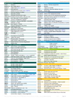
8 Anyone making use of thisinformation assumes all liability arising from such must be exercised when relying upon other specificationsand codes developed by other bodies and incorporated by referenceherein since such material may be modified or amended from timeto time subsequent to the printing of this Institute bearsno responsibility for such material other than to refer to it andincorporate it by reference at the time of the initial publication ofthis To Use The beam load TablesExample 1A simply supported 20 in. x 12 in. x 3/8 in. ERW HSS beam of Fy = 46 ksi (ASTM A500 Gr. B) spans 22 feet. The beam is laterallybraced for its entire length. Determine the uniform load capacity forloading in the plane of the minor the Fy = 46 load table for the HSS20x12x3/8 (page 6). Readacross the row at the span equal to 22 feet and note that the maximumfactored uniform load is equal to 167 kips. Note that this includes theweight of the HSS 2 Select the lightest 8-inch deep, simply supported ERW HSS beam ofFy = 50 ksi (ASTM A500 Gr.)
9 C) to span 8 feet and support a maximumfactored uniform load of 52 kips (includes the estimated weight of theHSS beam ). The beam is laterally supported for its entire the Fy = 50 ksi load Tables for the 8-in. deep rectangular and 8 in. deep square HSS. Note that the maximum factored uniform loadcapacity for a:HSS8x8x1/4( ) = 70 kips > 52 kips ( ) = 46 kips < 52 kips not goodHSS8x6x1/4( ) = 63 kips > 52 kips ( ) = 43 kips < 52 kips not goodHSS8x4x5/16( ) = 60 kips > 52 kips ( ) = 50 kips < 52 kips not goodHSS8x3x5/16( ) = 52 kips > 52 kips ( ) = 43 kips < 52 kips not goodSelect: HSS8x3x5/16 (weight = lbs. per ft.)924694541115092469479461652292469454 1102083964654163549341786561145285169953 8454529411348741524387729599461389453352 2986494583396385244043403973082615774073 0156746635930235327423251936727151142032 3272317246209472333246464381294247289224 1904323062264263502692272652051743992822 0939332324820924419016137126219436530023 1194227176149346244181340280215181212164 1393242291693192622021701981541303052161 5930024719016018714512328820415128423317 9151176137116273193143269221170143167130 1102601831362552101611361591231042471751 2924320015413015111799236167123232191147 1241441129522615911822218214011813810791 2161531132131751351131321038720814710820 4168129109127998320014110419616112410512 2958019213610018915512010111891771851319 7182150115971138875179126931761451119410 9857217312290170140108911068270167118871 6513510488102806716211585160131101859977 6515711182155127988296756315310880150123 9580937261144102751421179076886858137977 1134110857284655513092681281058168796252 1248765122100776576595011883621169573627 2564711380591119170596954451087656106876 7576651431047354102846554634942Ix, , , vVn, (kips) bWc, (kip-ft)Nominal SizeWall ThicknessWeight Per FootDesign Wall Thickness6xxyyFy=46 lrfd BeamsRectangular HSSM aximum Factored Uniform Loads in Kips for Beams Laterally SupportedERWE ffective length KL in feet345678910111213141516171819202122232 42526272829303132333436384042444648501/2 3/85/165/81/23/85/161/23/85 * x 1220 x 820 x 4Fy= 46 ksiPROPERTIESLoad above heavy horizontal line is limited by design shear strength.
10 * Section contains slender compression element; > r.** Effective section modulus, Seff, calculated in accordance with AISC HSS Specification" Section (b). ** , , , vVn, (kips) bWc, (kip-ft)Nominal SizeWall ThicknessWeight Per FootDesign Wall Thickness75/81/23/85/161/41/23/85/165/81 /23/85 * length KL in feet345678910111213141516171819202122232 425262728293031323334353637383941434518 x 616 x 1216 x 8Fy= 46 ksiPROPERTIES xxyyFy=46 lrfd BeamsRectangular HSSM aximum Factored Uniform Loads in Kips for Beams Laterally SupportedERWLoad above heavy horizontal line is limited by design shear strength.* Section contains slender compression element; > r.** Effective section modulus, Seff, calculated in accordance with AISC HSS Specification" Section (b). ** , , , vVn, (kips) bWc, (kip-ft)Nominal SizeWall ThicknessWeight Per FootDesign Wall ** length KL in feet023456789101112131415161718192021222 324252627282930313233343536373839401/23/ 85/165/81/23/85/161 *739555711554463324533415353808647485405 2924273322826625454213302343562772355524 5435127519530523720147339030123616726720 8176414341263206146237185157368303234184 1302131661413312732111651171941511283012 4819115010617813811827622717513897164128 1082552101621279015211910123719515011883 1421119422118214011078133104882071701321 0373125988319516012497691199278184151117 9265112877417414411187611078371166136105 8358102796715813010079569776641511249675 5393726114411992725189695913811488694985 6656132109846647826454127105816445796252 1231017861437659501189775594274574911494 7357407155471109170553969544510788685338 6752441048566523665504310083645035634941 9780624934614740957860473359463958453856 443755433653423516 x 414 x 10Fy= 46 ksiPROPERTIES