Transcription of LS200, LS200N, LS200NDVOR Series and L1100 …
1 ls200 , ls200n , ls200 NDVOR Series and L1100 Liquid Level Switches Installation and Operations manual 00-02-0671. 09-15-08. Section 15. In order to consistently bring you the highest quality full featured products, we reserve the right to change our specifications and designs at any time. The latest version of this manual can be found at Warranty - A limited warranty on materials and workmanship for one year is given with this FW Murphy product. A copy of the warranty may be viewed or printed by going to CAUTION: ls200 Series parts are not interchangeable with other Murphy liquid level products. Damage caused by using incorrect parts is not covered by our Limited Warranty. Please read the following information before installing. A visual inspection for damage during shipping is recommended before mounting. BEFORE BEGINNING INSTALLATION OF THIS MURPHY.
2 PRODUCT: Disconnect all electrical power to the machine. Make sure the machine cannot operate during installation. Follow all safety warnings of the machine manufacturer. Read and follow all installation instructions. OBSERVE all pressure and electrical ratings and require- ments for the devices and the operating environment. BE SURE all pressure HAS BEEN REMOVED from the vessel before opening any pressure connections. Please contact FW MURPHY immediately if you have any questions. Table of Contents Product 1. Features ..1. ls200 , ls200 NDVO ..3. ls200n ..3. Pressure Vessel Installation: ls200 , ls200n and 4. Direct Installation into the Wall of the Pressure Vessel ..4. Installation with a Weld Collar ..5. Installation Using Murphy External Float Chamber ..5. Installation and Adjustment for Pneumatic Replacing and Installing the DVO 7.
3 Models ls200 NDVO & ls200 NDVOR ..7. Electrical .. 10. Replacement 10. Accessories .. 11. 15050375: Weld 55050617: DVU150/DVU175 Adapter 15051098: External Float Chamber ..11. 15700799: Series 100 External Float Chamber ..12. 15000478: Float Shaft Extension for the 15000892: Float Shaft Extension for the L1100 ..12. The Murphy Gas Compressor Scrubber Level System (SLS) ..13. 14. All ls200 NDVO ..14. ls200 N ..14. L1100 ..14. Approximate Shipping Weights and (THIS PAGE INTENTIONALLY LEFT BLANK). Product Information Features Designed for harsh gas compressor scrubber applications 304 stainless steel float ls200 Series rated for 2000 psi ( MPa) [138 bar] working pressure Electric and pneumatic models available Improved design provides better dependability with reduced number of moving parts All models screw directly into the vessel or can be mounted via external float chamber Nickel plated body to provide enhanced corrosion protection Listed for Class I, Div.
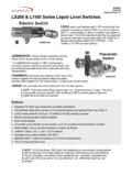
4 1, Grp. C & D locations Canadian Registration Number Minimum Allowable Specific Gravity for ls200 . Table 1. ls200 Minimum Allowable Specific Gravity Model Float Extension Pressure Specific length Gravity (inch) (psi). 0 ls200 1 2000 6 1. 0 ls200 NDVO 1 2000 6 *Note: The min. allowable SG will decrease with a decrease in operating pressure ls200 , L1100 . ls200 Liquid Level Switches with 2 NPT mounting are float activated to operate an electrical SPDT snap switch (optional DPDT on some models) for alarm or shutdown of an engine or electric motor. The ls200 connects directly into the vessel wall and can be used with a Murphy weld collar (P/N 15050375) or Murphy external float chamber. Section 15 00-02-0671. 09-15-08 -1- L1100 models (1-1/2 NPT) are also available. Refer to the specification table below for product dimensions.
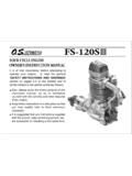
5 Table 2. ls200 L1100 . A in. (258 mm) 11 in. (279 mm). B in. (87 mm) in. (189 mm). C in. (44 mm) in. (40 mm). D in. (71 mm) in. (71 mm). ls200 , L1100 E 2 NPT 1-1/2 NPT. NOTE: Refer to Table 3 and Table 4 for clearances. ls200 NDVOR. ls200 NDVOR is a float-activated, pneumatic-vent level device used to operate dump valves or similar devices. The ls200 NDVOR provides a 2 NPT mounting with a pneumatic output for interfacing with pneumatic devices such as our Murphy pneumatic dump valve or with other pneumatic instrumentation. Pneumatic media devices require clean, dry, instrument quality air or gas. This unit is supplied with a pressure regulator, filter and Murphy 20 BPG pressure gage for improved system life and trouble-free operation. ls200 NDVOR pneumatic level switch with dump valve operator, pressure regulator and gage Section 15 00-02-0671.
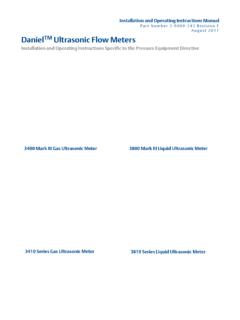
6 09-15-08 -2- ls200 NDVO. Pneumatic level switch with Dump Valve Operator (DVO) without the pressure regulator for those applications where the system provides a filter regulator for instrument quality air or gas as the control medium. ls200 NDVO pneumatic level switch with dump valve operator ls200n . Pneumatic level switch without the DVO and filter regulator. ls200n pneumatic level switch Section 15 00-02-0671. 09-15-08 -3- Pressure Vessel Installation: ls200 , ls200n and L1100 . Direct Installation into the Wall of the Pressure Vessel CAUTION: Determine that the float travel is not obstructed by the coupling in the vessel wall, internal baffles, etc. Refer to tables 1, 2, 3 and 4 for application data. 1. Make certain the float and extension are tight. 2. Before installing the level switch, use of a pipe thread sealant is recommended.
7 Screw the unit directly into the threaded connection in the wall of the pressure vessel. 3. For ls200 and L1100 , verify that the electrical connection is positioned at the bottom. 4. For ls200n the 1/8 NPT pneumatic connection should be on top, the 3/8 NPT vent connection should be on the bottom. 5. Make the electrical wiring connections according to appropriate wiring diagrams for the alarm or shutdown system to be used. The electrical connection is 1/2 -14 NPT. 6. Ensure all electrical connections are insulated and the cover is fully installed before reconnecting electrical power. 7. Verify all pressure connections are tight before pressurizing the system. Clearance Reference Tables Table 3. Pipe Data Nom. Size Schedule Wall Thickness Inside Diameter (inches) (inches) Number (inches) (inches). 3 40ST 3 80XS 4 40ST 4 80XS Table 4.
8 Minimum Clearance Product Name Insertion Depth (inches) Vertical Clearance (inches). Std. w/ 1 Extension Std. w/ 1 Extension LS 200 LS 200N L 1200 L 1200N L 1100 Section 15 00-02-0671. 09-15-08 -4- Installation with a Weld Collar 1. The weld collar, P/N 15050375, must be welded into the wall of the pressure vessel according to code standards and good welding practices. 2. Follow above instructions for installation directly into the wall of the pressure vessel. NOTE: Weld collar 15050375 can be used ONLY with model ls200 . Installation Using Murphy External Float Chamber 1. Install the Murphy float chamber 15051098 or 15700799 on the outside wall of the pressure vessel using 1 NPT piping or use the mounting surface with a bracket. Position the 2 NPT threaded connection at the height where you want the level switch to operate.
9 The 2 NPT threaded connection must be positioned away from the tank wall. 2. A tee and bleed valve are typically installed at the bottom of the lower 1 inch pipe riser to allow draining of the float chamber for servicing or replacement. NOTE: A typical installation with blocking and bleed valves is shown at right. 3. Install the ls200 or ls200n /NDVO/NDVOR in the 2 NPT connection of the float chamber. BE SURE. float travel is not restricted and that the float is tight onto the float shaft. 4. To complete installation and wiring, follow the instructions for mounting directly into wall of the vessel and for wiring. CAUTION: Float extensions cannot be used with float chambers. Section 15 00-02-0671. 09-15-08 -5- Installation and Adjustment for Pneumatic Models 1. All pneumatic models operate on the vent principle.
10 The pneumatic signal source must be clean and dry Instrument Quality air or natural gas. The input pneumatic signal must be regulated between 30 and 70 psi (207-483 kPa) [2 bar]. If produced gas is used as the signal source, it should be taken after gas passes through the final scrubber. A. suitable filter must be positioned before the ls200 NDVO to prevent liquids and/or particulates from entering the dump valve operator. NOTE: Check filter periodically for wear and tear and elements that hamper the flow of the pneumatic signal. 2. All pressure connections must be tight and maintained tight so as not to leak air/gas. CAUTION: Avoid excessive Teflon tape which may inhibit proper operation. Each switch is set to vent on rising level at the factory and should not need field adjustment. For testing the system, Murphy has provided the red " manual Valve Operator" on the operator pilot valve.