Transcription of LT1097 - Low Cost, Low Power Precision Op Amp
1 LT1097 . Low Cost, Low Power Precision Op Amp U. FEATURES DESCRIPTION. Offset Voltage 50 V Max LT 1097 achieves a new standard in combining low price Offset Voltage Drift 1 V/ C Max and outstanding Precision performance. Bias Current 250pA Max On all operational amplifier data sheets, the specifications Offset Current 250pA Max listed on the front page are for highly selected, expensive Bias and Offset Current Drift 4pA/ C Max grades, while the specs for the low cost grades are buried Supply Current 560 A Max deep in the data sheet. to 10Hz Noise Vp-p, CMRR 115dB Min The LT1097 does not have any selected grades, the Voltage Gain 117dB Min outstanding specifications shown in the Features section PSRR 114dB Min are for its only grade. Guaranteed Operation on Two NiCad Batteries The design effort of the LT1097 concentrated on optimiz- ing the performance of all Precision specs at only 350 A. U of supply current. Typical values are 10 V offset voltage, APPLICATIONS 40pA bias and offset currents, V/ C and C.
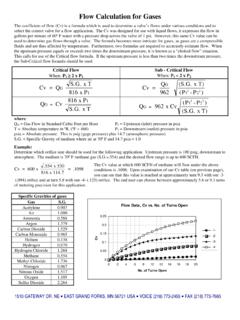
2 Replaces OP-07/OP-77/OP-97/OP-177/AD707/ drift. Common mode and Power supply rejections, voltage LT1001 with Improved Price/Performance gain are typically in excess of 128dB. High Impedance Difference Amplifiers All parameters that are important for Precision , low Power Logarithmic Amplifiers (Wide Dynamic Range). op amps have been optimized. Consequently, using the Thermocouple Amplifiers LT1097 error budget calculations in most applications is Precision Instrumentation unnecessary. Active Filters (with Small Capacitors). , LTC and LT are registered trademarks of Linear Technology Corporation. U. TYPICAL APPLICATION. Saturated Standard Cell Amplifier Input Offset Voltage Distribution 9V 50. 6,500 UNITS IN SO PACKAGE. 2N3609. 6,680 UNITS IN. 3 7 PLASTIC. + 40. DIP VS = 15V. 6 13,180 UNITS TA = 25 C. PERCENT OF UNITS. LT1097 OUT = TO 2 AS R2 135k TESTED. 30. + . 4. SATURATED 20. STANDARD. CELL #101. EPPLEY LABS 10. R1 R2. NEWPORT, R. I. 20k THE TYPICAL 40pA BIAS CURRENT OF THE LT1097 .
3 WILL DEGRADE THE STANDARD CELL BY ONLY 0. 1ppm/YEAR. NOISE IS A FRACTION OF A ppm. 50 40 30 20 10 0 10 20 30 40 50. UNPROTECTED GATE MOSFET ISOLATES INPUT OFFSET VOLTAGE ( V). STANDARD CELL ON Power DOWN. LT1097 G01. LT1097 TA01. 1. LT1097 . W W W U. ABSOLUTE MAXIMUM RATINGS. Supply Voltage .. 20V Operating Temperature Range .. 40 C to 85 C. Differential Input Current (Note 1) .. 10mA Storage Temperature Range .. 65 C to 150 C. Input Voltage .. 20V Lead Temperature (Soldering, 10 sec).. 300 C. Output Short Circuit Duration .. Indefinite U W U. PACKAGE/ORDER INFORMATION. TOP VIEW TOP VIEW. ORDER ORDER. VOS TRIM 1 8 VOS TRIM PART NUMBER VOS TRIM 1 8 VOS TRIM PART NUMBER. IN 2 7 V+ IN 2 7 V+. LT1097CN8 LT1097S8. +IN 3 6 OUT +IN 3 6 OUT. V 4 5 OVER COMP V 4 5 OVER COMP. N8 PACKAGE S8 PACKAGE. 8-LEAD PLASTIC DIP 8-LEAD PLASTIC SO. ELECTRICAL CHARACTERISTICS VS = 15V, VCM = 0V, TA = 25 C, unless otherwise noted. LT1097CN8 LT1097S8. SYMBOL PARAMETER CONDITIONS MIN TYP MAX MIN TYP MAX UNITS.
4 VOS Input Offset Voltage 10 50 10 60 V. VOS Long Term Input Offset V/Mo TIME Voltage Stability IOS Input Offset Current 40 250 60 350 pA. IB Input Bias Current 40 250 50 350 pA. en Input Noise Voltage to 10Hz Vp-p Input Noise Voltage Density fO = 10Hz 16 16 nV/ Hz fO = 1000Hz 14 14 nV/ Hz in Input Noise Current to 10Hz pAp-p Input Noise Current Density fO = 10Hz pA/ Hz fO = 1000Hz pA/ Hz Input Resistance (Note 2). Differential Mode 30 80 25 70 M . Common Mode 1012 8 1011 . Input Voltage Range V. CMRR Common Mode Rejection Ratio VCM = 115 130 115 130 dB. PSRR Power Supply Rejection Ratio VS = to 20V 114 130 114 130 dB. AVOL Large Signal Voltage Gain VO = 12V, RL = 10k 700 2500 700 2500 V/mV. VO = 10V, RL = 2k 250 1000 250 1000 V/mV. VOUT Output Voltage Swing RL = 10k 13 13 V. RL = 2k 13 13 V. SR Slew Rate V/ s GBW Gain Bandwidth Product 700 700 kHz IS Supply Current 350 560 350 560 A. Offset Adjustment Range RPOT = 10k, Wiper to V+ 600 600 V. Minimum Supply Voltage (Note 3) V.
5 2. LT1097 . ELECTRICAL CHARACTERISTICS VS = 15V, VCM = 0V, 0 C TA 70 C, unless otherwise noted. LT1097CN8 LT1097S8. SYMBOL PARAMETER CONDITIONS MIN TYP MAX MIN TYP MAX UNITS. VOS Input Offset Voltage 20 100 20 130 V. Average Temperature Coefficient of (Note 4) 1 V/ C. Input Offset Voltage IOS Input Offset Current 60 430 75 570 pA. Average Temperature Coefficient of (Note 4) 4 5 pA/ C. Input Offset Current IB Input Bias Current 60 430 75 570 pA. Average Temperature Coefficient of (Note 4) 4 5 pA/ C. Input Bias Current AVOL Large Signal Voltage Gain VOUT = 12V, RL 10k 450 2000 450 2000 V/mV. VOUT = 10V, RL 2k 180 800 180 800 V/mV. CMRR Common Mode Rejection Ratio VCM = 112 128 112 128 dB. PSRR Power Supply Rejection Ratio VS = to 20V 111 128 111 128 dB. Input Voltage Range V. VOUT Output Voltage Swing RL = 10k 13 13 V. IS Supply Current 380 700 380 700 A. ELECTRICAL CHARACTERISTICS VS = 15V, VCM = 0V, 40 C TA 85 C, unless otherwise noted. (Note 5). LT1097CN8 LT1097S8. SYMBOL PARAMETER CONDITIONS MIN TYP MAX MIN TYP MAX UNITS.
6 VOS Input Offset Voltage 25 130 30 170 V. Average Temperature Coefficient of V/ C. Input Offset Voltage IOS Input Offset Current 70 600 85 750 pA. Average Temperature Coefficient of 5 6 pA/ C. Input Offset Current IB Input Bias Current 70 600 85 750 pA. Average Temperature Coefficient of 5 6 pA/ C. Input Bias Current AVOL Large Signal Voltage Gain VOUT = 12V, RL 10k 300 1700 300 1700 V/mV. VOUT = 10V, RL 2k 700 700 V/mV. CMRR Common Mode Rejection Ratio VCM = 108 127 108 127 dB. PSRR Power Supply Rejection Ratio VS = to 20V 108 127 108 127 dB. Input Voltage Range 14 14 V. VOUT Output Voltage Swing RL = 10k 13 13 V. IS Supply Current 400 800 400 800 A. The denotes specifications which apply over the full operating Note 3: Power supply rejection ratio is measured at the minimum supply temperature range. voltage. Note 1: Differential input voltages greater than 1V will cause excessive Note 4: This parameter is not 100% tested. current to flow through the input protection diodes unless limiting Note 5: The LT1097 is designed, characterized and expected to meet these resistance is used.
7 Extended temperature limits, but is not tested at 40 C and 85 C. Note 2: This parameter is guaranteed by design and is not tested. Guaranteed I grade parts are available; consult factory. 3. LT1097 . U W. TYPICAL PERFORMANCE CHARACTERISTICS. Distribution to Offset Voltage Drift with Temperature 50. 40 VS = 15V. 240 UNITS TESTED. PERCENT OF UNITS. IN N8 PACKAGES. 30 FROM SIX RUNS. 20. 10. 0. 0 OFFSET VOLTAGE DRIFT WITH TEMPERATURE ( V/ C). LT1097 G02. Minimum Supply Voltage, Common Mode Range and Input Bias Current vs Temperature Voltage Swing at VMIN. V+ COMMON MODE RANGE OR OUTPUT SWING (V). 200. V+ MINIMUM SUPPLY VOLTAGE, VMIN (V). 100 V+ INPUT BIAS CURRENT (pA). UNDERCANCELLED UNIT. V+ CM RANGE 0 V+ SWING. RL = 10k 100 OVERCANCELLED UNIT V + SWING. V + CM RANGE. 200 V + V + 300 V . 50 25 0 25 50 75 100 40 10 20 50 80 110. TEMPERATURE ( C) TEMPERATURE ( C). 1097 G03 1097 G04. Input Bias Current Over Common Warm-Up Drift Mode Range 5 120. VS = 15V. VS = 15V TA = 25 C. CHANGE IN OFFSET VOLTAGE ( V).
8 TA = 25 C 80. 4 DEVICE WITH POSITIVE INPUT CURRENT. INPUT BIAS CURRENT (pA). 40. 3 RIN CM = 1012 . 0. DEVICE WITH NEGATIVE INPUT CURRENT. 2. 40. PLASTIC-IN-LINE PACKAGE . PLASTIC (N) OR SO (S) IB. 1. 80 VCM +. 0 120. 0 1 2 3 4 5 15 10 5 0 5 10 15. TIME AFTER Power ON (MINUTES) COMMON MODE INPUT VOLTAGE. 1097 G05 1097 G06. 4. LT1097 . U W. TYPICAL PERFORMANCE CHARACTERISTICS. Output Short Circuit Current vs Time 20. 15. SOURCING. SHORT CIRCUIT CURRENT (mA). 10. 5 VS = 15V. TA = 25 C. 0. 5. SINKING. 10. 15. 20. 0 1 2 3. TIME FROM OUTPUT SHORT (MINUTES). 1097 G07. to 10Hz Noise to 10Hz Noise VS = TO 20V VS = TO 20V. TA = 25 C TA = 25 C. NOISE VOLTAGE ( V/DIV). NOISE VOLTAGE ( V/DIV). V. 0 2 4 6 8 10 0 20 40 60 80 100. TIME (SECONDS) TIME (SECONDS). 1097 G08 1097 G09. Noise Spectrum Voltage Gain 1000 30. TA = 25 C Vs = 15 V. VS = TO 20V TA = 25 C. VOLTAGE NOISE DENSITY (nV Hz). CHANGE IN OFFSET VOLTAGE ( V). CURRENT NOISE DENSITY (fA Hz). 20. 100 10. CURRENT NOISE. RL = 10k 0 RL = 10k VOLTAGE NOISE.
9 RL = 2k 10 10 RL = 2k 1/f CORNER. 1/f CORNER 20. 140Hz 1 30. 1 10 100 1000 15 10 5 0 5 10 15. FREQUENCY (Hz) OUTPUT VOLTAGE (V). 1097 G10 1097 G11. 5. LT1097 . U W. TYPICAL PERFORMANCE CHARACTERISTICS. Voltage Gain vs Frequency 140. VS = 15V. 120 TA = 25 C. 100. VOLTAGE GAIN (dB). 80. 60. 40. 20. 0. 20. 1 10 100 1k 10k 100k 1M 10M. FREQUENCY (Hz). 1097 G12. Common Mode Rejection vs Gain, Phase Shift vs Frequency Frequency 40 100 140. VS = 15V VS = 15V. COMMON MODE REJCTION RATIO (dB). TA = 25 C 120 TA = 25 C. 30 PHASE 120. PHASE SHIFT (DEGREES). 100. GAIN. 20 140. GAIN (dB). 80. 60. 10 160. 40. 0 180. 20. PHASE MARGIN = 70 C. 10 200 0. 1 10 1 10 100 1k 10k 100k 1M. FREQUENCY (MHz) FREQUENCY (Hz). 1097 G13. 1097 G14. Slew Rate, Gain Bandwidth Power Supply Rejection vs Product vs Overcompensation Frequency Capacitor 140 1 1000. VS = 15V. Power SUPPLY REJECTION RATIO (dB). TA = 25 C. GAIN BANDWIDTH PRODUCT (kHz). 120. SLEW GBW. SLEW RATE (V/ s). 100 100. NEGATIVE SUPPLY. 80. POSITIVE SUPPLY.
10 60 10. 40 VS = 15V. TA = 25 C. 20 1. 1 10 100 1k 10k 100k 1M 1 10 100 1000 10000. FREQUENCY (Hz) OVERCOMPENSATION CAPACITOR (pF). 1097 G15 1097 G16. 6. LT1097 . U W. TYPICAL PERFORMANCE CHARACTERISTICS. Small Signal Transient Response Large Signal Transient Response 20mV/DIV. 2V/DIV. 1097 G17 1097 G18. AV = 1, CLOAD = 100pF, 5 s/DIV AV = 1, 20 s/DIV. Capacitive Load Handling 70. TA = 25 C. 60 VS = 15V. CS: PIN 5 TO GROUND. 50. OVERSHOOT (%). AV = 1. 40 CS = 0. 30. AV = 1. CS = 200pF. 20. 10 AV = 10. CS = 0. 0. 10 100 1000 10,000. CAPACITIVE LOAD (pF). 1097 G19. 7. LT1097 . W W. SCHEMATIC DIAGRAM. TRIM 1 TRIM 8 5 OVER COMP V+. 7. 800 800 . 20 A. 35 A 80 A. 30k 30k Q19. Q22. 30pF. Q33. Q21 Q25. Q6 Q27. Q5 Q29. Q8 S. Q4 Q24. 40 . Q7. 100 OUT. 3k Q13 6. IN S S S Q11 Q23 40 . 2 Q1 Q2 Q3. Q20. Q28. 50k J1. Q26. Q9 Q32. Q18. Q12. Q16. +IN. Q10. Q17. 3. 15 A 80 A Q30. 5 A Q31. Q14 Q15. 5 A. 16k 40 330 . V 4. Q1 Q4 ARE SUPERGAIN TRANSISTORS 1097 BD. 8. LT1097 . U U W U. APPLICATIONS INFORMATION.