Transcription of LT1716 - SOT-23, 44V, Over-The-Top, Micropower, …
1 LT1716 . SOT-23, 44V, Over-the-Top, Micropower, precision rail -to- rail Comparator FEATURES DESCRIPTION. n Operates from to 44V The LT 1716 comparator operates on any total power n Over-The-Top : Input Common Mode Range supply voltage between and 44V drawing 35 A of Extends 44V Above V , Independent of V+ quiescent current. The LT1716 has a unique input stage n Micropower: 35 A IQ that can be taken 44V above V , independent of V+ supply. n Offset Voltage: Max (Built-in resistors protect the inputs for faults below the n Valid Output with Either Input 5V Below V negative supply of up to 5V.) The inputs can withstand n rail -to- rail Output Swing 44V both differential and common mode.
2 N Output Can Drive Loads Above V+. n The output stage includes a class B pull-up current Internal Pull-Up Current n source, eliminating the need for an external resistive 40 C to 125 C Operating Temperature Range n pull-up and saving power. Output voltage swings to within Low Pro le (1mm) SOT-23 (ThinSOT ) Package 35mV of the negative supply and 55mV of the positive supply, which makes the comparator a good choice for APPLICATIONS low voltage single supply operation. The output stage is n also designed to drive loads connected to a higher supply Power Supply Monitors n than the LT1716 supply, the same as an open collector Relay/Lamp Driver n output stage.
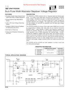
3 Oscillators n Peak Detector The LT1716 is available in a SOT-23 5-lead package. n Level Shifting L, LT, LTC, LTM, Over-The-Top, Linear Technology and the Linear logo are registered trademarks of Linear Technology Corporation. ThinSOT is a trademark of Linear Technology Corporation. All other trademarks are the property of their respective owners. TYPICAL APPLICATION. Lamp Monitor Input Bias Current vs Input Bias Voltage 12 . 5V TO 44V 3V F VS = 5V, 0V. 1M 8 . +IN = 10V. 4 INPUT INPUT. BELOW ABOVE. LAMP CMPD6001 6n SUPPLY SUPPLY. 100k ON/OFF 3n 5k 4 5.. IB (A). 0. RS 1 +IN = 2V +IN = 2V. LT1716 LAMP GOOD 3n 1W 3.
4 + 6n 2 100m TO RS 1716 TA01 IL. 1m 10 5 0 5 10 15 20 45. VIN (V). 1716 TA02. 1716fa 1. LT1716 . ABSOLUTE MAXIMUM RATINGS PIN CONFIGURATION. (Note 1). Supply Voltage (V+ to V ) ..44V TOP VIEW. Differential Input Voltage ..44V OUT 1 5 V+. Input , 5V V 2. + . Output Short-Circuit Duration (Note 2) .. Inde nite +IN 3 4 IN. Operating Temperature Range (Note 3) S5 PACKAGE. 5-LEAD PLASTIC TSOT-23. LT1716C/LT1716I .. 40 C to 85 C. TJMAX = 150 C, JA = 250 C/W. 40 C to 125 C. Speci ed Temperature Range (Note 4). LT1716C/LT1716I .. 40 C to 85 C. 40 C to 125 C. Maximum Junction Temperature .. 150 C. Storage Temperature Range.
5 65 C to 150 C. Lead Temperature (Soldering, 10 sec).. 300 C. ORDER INFORMATION. LEAD FREE FINISH TAPE AND REEL PART MARKING* PACKAGE DESCRIPTION SPECIFIED TEMPERATURE RANGE. LT1716CS5#PBF LT1716CS5#TRPBF LTYD 5-Lead Plastic TSOT-23 40 C to 85 C. LT1716IS5#PBF LT1716IS5#TRPBF LTYD 5-Lead Plastic TSOT-23 40 C to 85 C. LT1716HS5#PBF LT1716HS5#TRPBF LTYD 5-Lead Plastic TSOT-23 40 C to 125 C. Consult LTC Marketing for parts speci ed with wider operating temperature ranges. *The temperature grade is identi ed by a label on the shipping container. Consult LTC Marketing for information on non-standard lead based nish parts.
6 For more information on lead free part marking, go to: For more information on tape and reel speci cations, go to: ELECTRICAL CHARACTERISTICS The l denotes the speci cations which apply over the full operating temperature range of 40 C TA 85 C, otherwise speci cations are at TA = 25 C. Single supply operation V+ = 5V, V = 0V;. VCM = V+/2 unless otherwise noted. (Note 4). LTC1716C/LT1716I. SYMBOL PARAMETER CONDITIONS MIN TYP MAX UNITS. VOS Input Offset Voltage < VCM < (VCC 1V) 300 1600 V. 0 C < TA < 70 C l 2100 V. 40 C < TA < 85 C l 2500 V. Input Offset Voltage Drift (Note 5) 0 C < TA < 70 C l 2 V/ C.
7 40 C < TA < 85 C l 2 V/ C. IOS Input Offset Current VCM = V+/2 l 3 15 nA. VCM = 0V l A. VCM = 44V l A. IB Input Bias Current VCM = V+/2 20 50 nA. l 35 75 nA. V+ = 0V, VCM = 44V 2 nA. VCM = 0V l 3 13 A. VCM = 44V l 6 9 A. VCM = 5V l 1 mA. Input Voltage Range (Note 7) l 44 V. CMRR Common Mode Rejection Ratio VCM < (V+ 1V) l 89 110 dB. VCM < 44V (Note 6) l 81 110 dB. 1716fa 2. LT1716 . ELECTRICAL CHARACTERISTICS The l denotes the speci cations which apply over the full operating temperature range of 40 C TA 85 C, otherwise speci cations are at TA = 25 C. Single supply operation V+ = 5V, V = 0V;. VCM = V+/2 unless otherwise noted.
8 (Note 4). LTC1716C/LT1716I. SYMBOL PARAMETER CONDITIONS MIN TYP MAX UNITS. PSRR Power Supply Rejection Ratio V = 0V, VCM = ; < V+ < 36V l 95 110 dB. Minimum Operating Supply Voltage l V. AVOL Large-Signal Voltage Gain RL = 1k; 1V < VOUT < 4V 200 500 V/mV. l 100 V/mV. IS Supply Current V+ = 3V, RL = Open, VO = High 35 50 A. l 65 A. V+ = 5V, RL = Open, VO = High 35 55 A. l 75 A. V+ = 12V, RL = Open, VO = High 40 60 A. l 85 A. ISC Output Sink Current (Note 2) VOVERDRIVE > 30mV l 10 20 mA. ISC+ Output Source Current VOVERDRIVE = 5mV, VOUT = 1V l 60 85 A. VOL Output Voltage Swing Low ISINK = 0mA, VOVERDRIVE = 10mV l 20 35 mV.
9 (Referred to V ) ISINK = l 75 110 mV. ISINK = 1mA l 200 300 mV. ISINK = 5mA l 550 900 mV. VOH Output Voltage Swing High ISOURCE = 0 A, VOVERDRIVE = 10mV l 30 55 mV. (Referred to V+) ISOURCE = 10 A l 130 185 mV. Leakage Current VOUT = 40V, VOVERDRIVE > 100mV l 2 A. Propagation Delay VOVERDRIVE > 100mV, RLOAD = 10k 3 s The l denotes the speci cations which apply over the full operating temperature range of 40 C TA 85 C, otherwise speci cations are at TA = 25 C. Split supply operation VS = 15V, VCM = 0V unless otherwise noted. (Note 4). LT1716C/LT1716I. SYMBOL PARAMETER CONDITIONS MIN TYP MAX UNITS. VOS Input Offset Voltage < VCM < 14V 300 1500 V.
10 0 C < TA < 70 C l 2000 V. 40 C < TA < 85 C l 2400 V. Input Offset Voltage Drift (Note 5) 0 C < TA < 70 C l 2 V/ C. 40 C < TA < 85 C l 2 V/ C. IOS Input Offset Current VCM = 0V l 3 15 nA. VCM = 29V l A. VCM = 15V l A. IB Input Bias Current VCM = 0V 30 60 nA. l 50 100 nA. VCM = 29V l 6 9 A. VCM = 15V l 3 13 A. VCM = 20V l 1 mA. Input Voltage Range (Note 7) l 14 V. CMRR Common Mode Rejection Ratio < VCM < 14V l 92 110 dB. < VCM < 29V (Note 6) l 81 98 dB. PSRR Power Supply Rejection Ratio VS = to 22V l 90 110 dB. Minimum Operating Supply Voltage l V. AVOL Large-Signal Voltage Gain RL = 6k; 14V < VOUT < 14V 500 1000 V/mV.