Transcription of LT1818/LT1819 - 400MHz, 2500V/μs, 9mA Single/Dual ...
1 LT1818/LT1819 . 400 MHz, 2500V/ s, 9mA. Single/Dual Operational Amplifiers FEATURES DESCRIPTION. n 400 MHz Gain Bandwidth Product The LT 1818/LT1819 are Single/Dual wide bandwidth, high n 2500V/ s Slew Rate slew rate, low noise and distortion operational ampli ers n 85dBc Distortion at 5 MHz with excellent DC performance. The LT1818/LT1819 have n 9mA Supply Current Per Ampli er been designed for wider bandwidth and slew rate, much n 6nV/ Hz Input Noise Voltage lower input offset voltage and lower noise and distortion n Unity-Gain Stable than devices with comparable supply current. The circuit n Maximum Input Offset Voltage topology is a voltage feedback ampli er with the excellent n 8 A Maximum Input Bias Current slewing characteristics of a current feedback ampli er.
2 N 800nA Maximum Input Offset Current n The output drives a 100 load to with 5V sup- 40mA Minimum Output Current, VOUT = 3V. n plies. On a single 5V supply, the output swings from 1V. Minimum Input CMR, VS = 5V. n to 4V with a 100 load connected to The ampli er Speci ed at 5V, Single 5V Supplies n is unity-gain stable with a 20pF capacitive load without the Operating Temperature Range: 40 C to 85 C. n need for a series resistor. Harmonic distortion is 85dBc Low Pro le (1mm) TSOT-23 (ThinSOT ) Package up to 5 MHz for a 2VP-P output at a gain of 2. APPLICATIONS The LT1818/LT1819 are manufactured on Linear tech - n nology 's advanced low voltage complementary bipolar Wideband Ampli ers n process. The LT1818 (single op amp) is available in Buffers n TSOT-23 and SO-8 packages; the LT1819 (dual op amp).
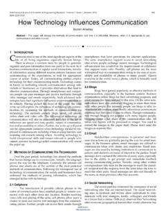
3 Active Filters n is available in MSOP-8 and SO-8 packages. Video and RF Ampli cation L, LT, LTC, LTM, Linear Technology and the Linear logo are registered trademarks of Linear n Communication Receivers Technology Corporation. ThinSOT is a trademark of Linear Technology Corporation. n Cable Drivers All other trademarks are the property of their respective owners. n Data Acquisition Systems TYPICAL APPLICATION. FFT of Single Supply ADC Driver 0. Single Supply Unity-Gain ADC Driver for Oversampling Applications 10. fIN = fS = 50 Msps 20 VIN = 300mVP-P. 5V 5V SFDR = 78dB. 30 8192 POINT FFT. AMPLITUDE (dBc). 40 NO WINDOWING. 1 VAC. + OR AVERAGING. LTC1744 50. LT1818 AIN+ 14 BITS. 50 Msps 60. 18pF.
4 AIN (SET FOR 2VP-P 70. FULL SCALE) 2 3. 80. 90. 18189 TA01. 100. 110. 0 5M 10M 15M 20M 25M. FREQUENCY (Hz). 18189 TA02. 18189fb 1. LT1818/LT1819 . ABSOLUTE MAXIMUM RATINGS (Note 1). Total Supply Voltage (V+ to V ) .. Speci ed Temperature Range (Note 9) .. 40 C to 85 C. Differential Input Voltage (Transient Only, Note 2).. 6V Maximum Junction 150 C. Output Short-Circuit Duration (Note 3) .. Inde nite Storage Temperature 65 C to 150 C. Operating Temperature Range (Note 8).. 40 C to 85 C Lead Temperature (Soldering, 10 sec) .. 300 C. PIN CONFIGURATION. TOP VIEW. TOP VIEW. OUT 1 1 5 V+ OUT A 1 8 V+. IN A 2 7 OUT B. V 2 A. +IN A 3 6 IN B. + B. +IN 3 4 IN V 4 5 +IN B. MS8 PACKAGE. S5 PACKAGE 8-LEAD PLASTIC MSOP.
5 5-LEAD PLASTIC TSOT-23. TJMAX = 150 C, JA = 250 C/W (NOTE 10). TJMAX = 150 C, JA = 250 C/W (NOTE 10). TOP VIEW TOP VIEW. NC 1 8 NC OUT A 1 8 V+. IN 2 7 V+ IN A 2 7 OUT B. + A. +IN 3 6 OUT +IN A 3 6 IN B. B. V 4 5 NC V 4 5 +IN B. S8 PACKAGE S8 PACKAGE. 8-LEAD PLASTIC SO 8-LEAD PLASTIC SO. TJMAX = 150 C, JA = 150 C/W (NOTE 10) TJMAX = 150 C, JA = 150 C/W (NOTE 10). ORDER INFORMATION. LEAD FREE FINISH TAPE AND REEL PART MARKING* PACKAGE DESCRIPTION SPECIFIED TEMPERATURE RANGE. LT1818CS5#PBF LT1818CS5#TRPBF LTF7 5-Lead Plastic TSOT-23 0 C to 70 C. LT1818IS5#PBF LT1818IS5#TRPBF LTF7 5-Lead Plastic TSOT-23 40 C to 85 C. LT1818CS8#PBF LT1818CS8#TRPBF 1818 8-Lead Plastic SO 0 C to 70 C. LT1818IS8#PBF LT1818IS8#TRPBF 1818I 8-Lead Plastic SO 40 C to 85 C.
6 LT1819 CMS8#PBF LT1819 CMS8#TRPBF LTE7 8-Lead Plastic MSOP 0 C to 70 C. LT1819 IMS8#PBF LT1819 IMS8#TRPBF LTE5 8-Lead Plastic MSOP 40 C to 85 C. LT1819CS8#PBF LT1819CS8#TRPBF 1819 8-Lead Plastic SO 0 C to 70 C. LT1819IS8#PBF LT1819IS8#TRPBF 1819I 8-Lead Plastic SO 40 C to 85 C. Consult LTC Marketing for parts speci ed with wider operating temperature ranges. *The temperature grade is identi ed by a label on the shipping container. Consult LTC Marketing for information on non-standard lead based nish parts. For more information on lead free part marking, go to: For more information on tape and reel speci cations, go to: 18189fb 2. LT1818/LT1819 . ELECTRICAL CHARACTERISTICS The l denotes the speci cations which apply over the full operating temperature range, otherwise speci cations are at TA = 25 C.
7 (Note 9) VS = 5V, VCM = 0V, unless otherwise noted. SYMBOL PARAMETER CONDITIONS MIN TYP MAX UNITS. VOS Input Offset Voltage (Note 4) mV. TA = 0 C to 70 C l mV. TA = 40 C to 85 C l mV. VOS/ T Input Offset Voltage Drift TA = 0 C to 70 C (Note 7) l 10 15 V/ C. TA = 40 C to 85 C (Note 7) l 10 30 V/ C. IOS Input Offset Current 60 800 nA. TA = 0 C to 70 C l 1000 nA. TA = 40 C to 85 C l 1200 nA. IB Input Bias Current 2 8 A. TA = 0 C to 70 C l 10 A. TA = 40 C to 85 C l 12 A. en Input Noise Voltage Density f = 10kHz 6 nV/ Hz in Input Noise Current Density f = 10kHz pA/ Hz RIN Input Resistance VCM = V + to V+ 5 M . Differential 750 k . CIN Input Capacitance pF. VCM Input Voltage Range Guaranteed by CMRR V.
8 (Positive/Negative) TA = 40 C to 85 C l V. CMRR Common Mode Rejection Ratio VCM = 75 85 dB. TA = 0 C to 70 C l 73 dB. TA = 40 C to 85 C l 72 dB. Minimum Supply Voltage Guaranteed by PSRR 2 V. TA = 40 C to 85 C l 2 V. PSRR Power Supply Rejection Ratio VS = 2V to 78 97 dB. TA = 0 C to 70 C l 76 dB. TA = 40 C to 85 C l 75 dB. AVOL Large-Signal Voltage Gain VOUT = 3V, RL = 500 V/mV. TA = 0 C to 70 C l V/mV. TA = 40 C to 85 C l V/mV. VOUT = 3V, RL = 100 6 V/mV. TA = 0 C to 70 C l V/mV. TA = 40 C to 85 C l V/mV. Channel Separation VOUT = 3V, LT1819 82 100 dB. TA = 0 C to 70 C l 81 dB. TA = 40 C to 85 C l 80 dB. VOUT Output Swing (Positive/Negative) RL = 500 , 30mV Overdrive V. TA = 0 C to 70 C l V.
9 TA = 40 C to 85 C l V. RL = 100 , 30mV Overdrive V. TA = 0 C to 70 C l V. TA = 40 C to 85 C l V. IOUT Output Current VOUT = 3V, 30mV Overdrive 40 70 mA. TA = 0 C to 70 C l 35 mA. TA = 40 C to 85 C l 30 mA. ISC Output Short-Circuit Current VOUT = 0V, 1V Overdrive (Note 3) 100 200 mA. TA = 0 C to 70 C l 90 mA. TA = 40 C to 85 C l 70 mA. SR Slew Rate AV = 1 2500 V/ s AV = 1 (Note 5) 900 1800 V/ s TA = 0 C to 70 C l 750 V/ s TA = 40 C to 85 C l 600 V/ s FPBW Full-Power Bandwidth 6VP-P (Note 6) 95 MHz 18189fb 3. LT1818/LT1819 . ELECTRICAL CHARACTERISTICS The l denotes the speci cations which apply over the full operating temperature range, otherwise speci cations are at TA = 25 C. (Note 9) VS = 5V, VCM = 0V, unless otherwise noted.
10 SYMBOL PARAMETER CONDITIONS MIN TYP MAX UNITS. GBW Gain-Bandwidth Product f = 4 MHz, RL = 500 270 400 MHz TA = 0 C to 70 C l 260 MHz TA = 40 C to 85 C l 250 MHz tr , tf Rise Time, Fall Time AV = 1, 10% to 90%, Step ns tPD Propagation Delay AV = 1, 50% to 50%, Step ns OS Overshoot AV = 1, , RL = 100 20 %. tS Settling Time AV = 1, , 5V 10 ns HD Harmonic Distortion HD2, AV = 2, f = 5 MHz, VOUT = 2VP-P , RL = 500 85 dBc HD3, AV = 2, f = 5 MHz, VOUT = 2VP-P , RL = 500 89 dBc dG Differential Gain AV = 2, RL = 150 %. dP Differential Phase AV = 2, RL = 150 DEG. IS Supply Current Per Ampli er 9 10 mA. TA = 0 C to 70 C l 13 mA. TA = 40 C to 85 C l 14 mA. The l denotes the speci cations which apply over the full operating temperature range, otherwise speci cations are at TA = 25 C.