Transcription of LTC2645 - Quad 12-/10-/8-Bit PWM to VOUT DACs …
1 LTC2645 . quad 12-/10-/8-Bit PWM. to VOUT DACs with 10ppm/ C Reference Features Description n No Latency PWM-to-Voltage Conversion The LTC 2645 is a family of quad 12-, 10-, and 8-bit PWM- n Voltage Output Updates and Settles within 8 s to-voltage output DACs with an integrated high accuracy, n 100kHz to 30Hz PWM Input Frequency low drift, 10ppm/ C reference in a 16-lead MSOP package. It n Max INL; 1 LSB Max DNL ( LTC2645 -12) has rail-to-rail output buffers and is guaranteed monotonic. n Guaranteed Monotonic n Pin-Selectable Internal or External Reference The LTC2645 measures the period and pulse width of the n to Supply Range PWM input signals and updates the voltage output DACs n to Input Voltage Range after each corresponding PWM input rising edge. The n Low Power: 4mA at 3V, <1 A Power-Down DAC outputs update and settle to 12-bit accuracy within n Guaranteed Operation from 40 C to 125 C. 8 s typically and are capable of sourcing and sinking up n 16-Lead MSOP Package to 5mA (3V) or 10mA (5V), eliminating voltage ripple and replacing slow analog filters and buffer amplifiers.
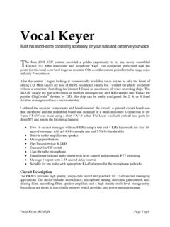
2 The LTC2645 has a full-scale output of using the Applications 10ppm/ C internal reference. It can operate with an exter- nal reference, which sets the full-scale output equal to the n Digital Calibration external reference voltage. Each DAC enters a pin-selectable n Trimming and Adjustment n idle state when the PWM input is held unchanged for more Level Setting n than 60ms. The part operates from a single to Process Control and Industrial Automation n supply and supports PWM input voltages from to Instrumentation L, LT, LTC, LTM, Linear Technology and the Linear logo are registered trademarks of Linear n Automotive Technology Corporation. All other trademarks are the property of their respective owners. Protected by Patents, including 5396245, 5859606, 6891433, 6937178, 7414561. Typical Application 4-Channel PWM to Voltage Output DAC. PWM Input to DAC Output PWM INPUTS. INA VOUTA. INB VOUTB BUFFERED INA. VOLTAGE 2V/DIV.
3 INC VOUTC OUTPUTS. IND VOUTD. TO LTC2645 . INPUT: 1V TO IOVCC REF. OUTPUT: TO F PD VCC. GND IDLSEL. F F. REFSEL VOUTA. 500mV/DIV. GND. TA01b 2645 TA01a 20 s/DIV. 2645fa For more information 1. LTC2645 . Absolute Maximum Ratings Pin Configuration (Notes 1, 2). Supply Voltages (VCC, IOVCC).. to 6V. INA, INB, INC, to 6V. TOP VIEW. IDLSEL, PD, to 6V VCC 1 16 GND. VOUTA, VOUTB, VOUTC, VOUTA 2. VOUTB 3. 15. 14. VOUTD. VOUTC. to Min (VCC + , 6V) IDLSEL 4. INB 5. 13. 12. REFSEL. REF. to Min (VCC + , 6V) INA 6 11 INC. IOVCC 7 10 IND. Operating Temperature Range GND 8 9 PD. 0 C to 70 C MS PACKAGE. 16-LEAD PLASTIC MSOP. 40 C to 85 C (4mm ). 40 C to 125 C TJMAX = 150 C, JA = 120 C/W. Maximum Junction 150 C. Storage Temperature 65 C to 150 C. Lead Temperature (Soldering, 10 sec).. 300 C. 2645fa 2 For more information LTC2645 . Order Information #orderinfo LTC2645 C MS L 12 #TR PBF. LEAD FREE DESIGNATOR. TAPE AND REEL. TR = 2,500-Piece Tape and Reel RESOLUTION.
4 12 = 12-Bit 10 = 10-Bit 8 = 8-Bit FULL-SCALE VOLTAGE, INTERNAL REFERENCE MODE. L = PACKAGE TYPE. MS = 16-Lead MSOP. TEMPERATURE GRADE. C = Commercial Temperature Range (0 C to 70 C). I = Industrial Temperature Range ( 40 C to 85 C). H = Automotive Temperature Range ( 40 C to 125 C). PRODUCT PART NUMBER. Consult LTC Marketing for parts specified with wider operating temperature ranges. For more information on lead free part marking, go to: For more information on tape and reel specifications, go to: Some packages are available in 500 unit reels through designated sales channels with #TRMPBF suffix. Product Selection Guide VFS WITH INTERNAL. PART NUMBER PART MARKING* RESOLUTION CHANNELS REFERENCE MAXIMUM INL PACKAGE DESCRIPTION. LTC2645 -L12 645L12 12-Bit 4 16-Lead Plastic MSOP. LTC2645 -L10 645L10 10-Bit 4 16-Lead Plastic MSOP. LTC2645 -L8 2645L8 8-Bit 4 16-Lead Plastic MSOP. *Temperature grades are identified by a label on the shipping container.
5 2645fa For more information 3. LTC2645 . Electrical Characteristics The l denotes the specifications which apply over the full operating temperature range, otherwise specifications are at TA = 25 C. VCC = to , VOUT unloaded unless otherwise specified. LTC2645 -L12/-L10/-L8 (VFS = ). LTC2645 -L8 LTC2645 -L10 LTC2645 -L12. SYMBOL PARAMETER CONDITIONS MIN TYP MAX MIN TYP MAX MIN TYP MAX UNITS. DC Performance Resolution l 8 10 12 Bits Monotonicity VCC = 3V, Internal Ref. (Note 3) l 8 10 12 Bits DNL Differential VCC = 3V, Internal Ref. (Note 3) l 1 LSB. Nonlinearity INL Integral Nonlinearity VCC = 3V, Internal Ref. (Note 3) l 1 1 LSB. ZSE Zero-Scale Error VCC = 3V, Internal Ref., Code = 0 l 5 5 5 mV. VOS Offset Error VCC = 3V, Internal Ref. (Note 4) l 5 5 5 mV. VOSTC VOS Temperature VCC = 3V, Internal Ref. (Note 9) 10 10 10 V/ C. Coefficient GE Gain Error VCC = 3V, Internal Ref. l %FSR. GETC Gain Temperature VCC = 3V, Internal Ref.
6 (Note 9). Coefficient C-grade 10 10 10 ppm/ C. I-grade 10 10 10 ppm/ C. H-grade 10 10 10 ppm/ C. Load Regulation Internal Ref., Mid-Scale, l LSB/mA. VCC = 3V 10%, 5mA IOUT 5mA. VCC = 5V 10%, l LSB/mA. 10mA IOUT 10mA. ROUT DC Output Internal Ref., Mid-Scale, l . Impedance VCC = 3V 10%, 5mA IOUT 5mA. VCC = 5V 10%, l . 10mA IOUT 10mA. SYMBOL PARAMETER CONDITIONS MIN TYP MAX UNITS. VOUT DAC Output Span External Reference 0 to VREF V. Internal Reference 0 to V. PSR Power Supply Rejection VCC = 3V 10% or 5V 10% 80 dB. ISC Short Circuit Output Current (Note 5) VFS = VCC = Sinking Zero-Scale; VOUT Shorted to VCC l 27 48 mA. Sourcing Full-Scale; VOUT Shorted to GND l 28 48 mA. Power Supply VCC Positive Supply Voltage For Specified Performance l V. IOVCC Digital Input Supply Voltage For Specified Performance l ICC Supply Current (Note 6) VCC = 3V, Internal Reference l 4 5 mA. VCC = 5V, Internal Reference l 8 mA. ICC(IOVCC) Supply Current, IOVCC (Note 6) IOVCC = 5V l 25 50 A.
7 ISD Supply Current in Power-Down Mode (Note 6) VCC = 5V, PD = 0V l 5 A. ISD(IOVCC) Supply Current in Power-Down Mode, IOVCC IOVCC = 5V, PD = 0V l 5 A. (Note 6). 2645fa 4 For more information LTC2645 . Electrical Characteristics The l denotes the specifications which apply over the full operating temperature range, otherwise specifications are at TA = 25 C. VCC = to , VOUT unloaded unless otherwise specified. LTC2645 -L12/-L10/-L8 (VFS = ). SYMBOL PARAMETER CONDITIONS MIN TYP MAX UNITS. Reference Input VREF Input Voltage Range l 1 VCC V. Resistance l 120 160 200 k . Capacitance pF. IREF Reference Current, Power-Down Mode DAC Powered Down l A. Reference Output Output Voltage l V. Reference Temperature Coefficient (Note 9) 10 ppm/ C. Output Impedance k . Capacitive Load Driving 10 F. Short Circuit Current VCC = , REF Shorted to GND mA. Digital Inputs (INA, INB, INC, IND, PD). VIH Digital Input High Voltage l IOVCC V.
8 VIL Digital Input Low Voltage l V. ILK Digital Input Leakage INA/INB/INC/IND = GND to IOVCC l 1 A. CIN Digital Input Capacitance (Note 7) l 5 pF. AC Performance ts Settling Time From INA/INB/INC/IND Rising Edge ( 1 LSB at 8 Bits) s (Note 8) ( 1 LSB at 10 Bits) s ( 1 LSB at 12 Bits) s Voltage Output Slew Rate V/ s Capacitive Load Driving 500 pF. Glitch Impulse At Mid-Scale Transition nV s DAC-to-DAC Crosstalk 1 DAC Held at FS, 1 DAC Switched 0 to FS nV s Multiplying Bandwidth External Reference 320 kHz en Output Voltage Noise Density At f = 1kHz, External Reference 180 nV/ Hz At f = 10kHz, External Reference 160 nV/ Hz At f = 1kHz, Internal Reference 200 nV/ Hz At f = 10kHz, Internal Reference 180 nV/ Hz Output Voltage Noise to 10Hz, External Reference 35 nVP-P. to 10Hz, Internal Reference 40 nVP-P. to 200kHz, External Reference 680 nVP-P. to 200kHz, Internal Reference 730 nVP-P. CREF = F. 2645fa For more information 5.
9 LTC2645 . Electrical Characteristics The l denotes the specifications which apply over the full operating temperature range, otherwise specifications are at TA = 25 C. VCC = to , VOUT unloaded unless otherwise specified. LTC2645 -L12/-L10/-L8 (VFS = ). SYMBOL PARAMETER CONDITIONS MIN TYP MAX UNITS. tPWH INA/INB/INC/IND High Time l 25 ns tPWL INA/INB/INC/IND Low Time l 25 ns tPER INA/INB/INC/IND Rising Edge to Rising Edge LTC2645 -L12 l 33 ms Period LTC2645 -L10 l 33 ms LTC2645 -L8 l 33 ms t3 INA/INB/INC/IND Idle Mode Timeout l 50 70 ms t4 INA/INB/INC/IND Rising Edge to DAC Update s Delay fMAX INA/INB/INC/IND Frequency LTC2645 -L12 l kHz LTC2645 -L10 l 25 kHz LTC2645 -L8 l 100 kHz Note 1: Stresses beyond those listed under Absolute Maximum Ratings Note 5: This IC includes current limiting that is intended to protect the may cause permanent damage to the device. Exposure to any Absolute device during momentary overload conditions.
10 Junction temperature can Maximum Rating condition for extended periods may affect device exceed the rated maximum during current limiting. Continuous operation reliability and lifetime. above the specified maximum operating junction temperature may impair Note 2: All voltages with respect to GND. device reliability. Note 3: Linearity and monotonicity are defined from code 16 to code 4095 Note 6: INx at 0V or IOVCC. ( LTC2645 -12), code 4 to code 1023 ( LTC2645 -10) or code 1 to code 255 Note 7: Guaranteed by design and not production tested. ( LTC2645 -8). Note 8: Internal Reference mode. DAC is stepped scale to scale and Note 4: Inferred from measurement at code 16 ( LTC2645 -12), code 4 scale to scale. Load is 2k in parallel with 100pF to GND. ( LTC2645 -10) or code 1 ( LTC2645 -8), and at full-scale. Note 9: Temperature coefficient is calculated by dividing the maximum change in output voltage by the specified temperature range.