Transcription of LTC4366 - High Voltage Surge Stopper - analog.com
1 LTC4366 . High Voltage Surge Stopper FEATURES DESCRIPTION. nn Rugged Floating Topology The LTC 4366 Surge Stopper protects loads from high nn Wide Operating Voltage Range: 9V to >500V Voltage transients. By controlling the gate of an external nn Adjustable Output Clamp Voltage N-channel MOSFET, the LTC4366 regulates the output nn Controls N-Channel MOSFET during an overvoltage transient. The load may remain nn Adjustable Protection Timer operational while the overvoltage is dropped across the nn Internal 9-Second Cool-Down Timer MOSFET. Placing a resistor in the return line isolates the nn Shutdown I < 14 A LTC4366 and allows it to float up with the supply; therefore, Q.
2 Nn 8-Lead TSOT and 3mm 2mm DFN Packages the upper limit on the output Voltage depends only on the availability of high valued resistors and MOSFET ratings. An adjustable overvoltage timer prevents MOSFET dam- APPLICATIONS age during the Surge while an additional 9-second timer provides for MOSFET cool down. A shutdown pin reduces nn Industrial, Automotive and Avionic Surge Protection the quiescent current to less than 14 A during shutdown. nn High Voltage DC Distribution nn 28V Vehicle Systems After a fault the LTC4366 -1 latches off while the LTC4366 2. will auto-retry. L, LT, LTC, LTM, Linear Technology and the Linear logo are registered trademarks and ThinSOT is a trademark of Linear Technology Corporation.
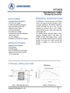
3 All other trademarks are the property of their respective owners. Patents pending. TYPICAL APPLICATION. Overvoltage Protected , 28V Supply Overvoltage Protector Regulates Output at 43V During Transient VIN IXTK90N25L2 VOUT. 28V 250V INPUT Surge . 10 2nF F VIN. 100V/DIV. 324k 28V. VDD GATE OUT SD LTC4366 -2 FB 43V CLAMP. VOUT. TIMER VSS BASE 422k 20V/DIV 28V. 1 F. 436612 TA01a 436612 TA01b 100ms/DIV. 436612fe For more information 1. LTC4366 . ABSOLUTE MAXIMUM RATINGS (Notes 1, 2) All voltages relative to VSS, unless otherwise noted. Supply Voltage (VDD) .. to 10V Currents Supply Voltage (OUT) .. to 5V Input Voltages IOUT ..10mA. to OUT + 300 A to 10 A.
4 To 10mA to 10 A. to 10V Operating Ambient Temperature Range (Note 4). Output Voltages 0 C to 70 C. to 4V 40 C to 85 C. OUT BASE .. to 40 C to 125 C. GATE (Note 3).. to 15V 55 C to 125 C. GATE OUT (Note 3).. to 10V Storage Temperature 65 C to 150 C. Lead Temperature (Soldering, 10 sec). TSOT-23 Package 300 C. PIN CONFIGURATION. TOP VIEW. TOP VIEW VSS 1 8 BASE. VDD 1 8 GATE TIMER 2 7 FB. SD 2 7 OUT 9. SD 3 6 OUT. TIMER 3 6 FB. VDD 4 5 GATE. VSS 4 5 BASE. TS8 PACKAGE. 8-LEAD PLASTIC TSOT-23 DDB PACKAGE. 8-LEAD (3mm 2mm) PLASTIC DFN. TJMAX = 150 C, JA = 195 C/W. TJMAX = 150 C, JA = 75 C/W IF VSS IS SOLDERED TO PCB, JA = 135 C/W IF VSS IS NOT SOLDERED TO PCB.
5 EXPOSED PAD (PIN 9), PCB VSS CONNECTION OPTIONAL. 436612fe 2 For more information LTC4366 . ORDER INFORMATION. Lead Free Finish TAPE AND REEL (MINI) TAPE AND REEL PART MARKING* PACKAGE DESCRIPTION TEMPERATURE RANGE. LTC4366 CTS8-1#TRMPBF LTC4366 CTS8-1#TRPBF LTFMC 8-Lead Plastic TSOT-23 0 C to 70 C. LTC4366 ITS8-1#TRMPBF LTC4366 ITS8-1#TRPBF LTFMC 8-Lead Plastic TSOT-23 40 C to 85 C. LTC4366 HTS8-1#TRMPBF LTC4366 HTS8-1#TRPBF LTFMC 8-Lead Plastic TSOT-23 40 C to 125 C. LTC4366 CDDB-1#TRMPBF LTC4366 CDDB-1#TRPBF LFMD 8-Lead (3mm 2mm) Plastic DFN 0 C to 70 C. LTC4366 IDDB-1#TRMPBF LTC4366 IDDB-1#TRPBF LFMD 8-Lead (3mm 2mm) Plastic DFN 40 C to 85 C.
6 LTC4366 HDDB-1#TRMPBF LTC4366 HDDB-1#TRPBF LFMD 8-Lead (3mm 2mm) Plastic DFN 40 C to 125 C. LTC4366 CTS8-2#TRMPBF LTC4366 CTS8-2#TRPBF LTFMF 8-Lead Plastic TSOT-23 0 C to 70 C. LTC4366 ITS8-2#TRMPBF LTC4366 ITS8-2#TRPBF LTFMF 8-Lead Plastic TSOT-23 40 C to 85 C. LTC4366 HTS8-2#TRMPBF LTC4366 HTS8-2#TRPBF LTFMF 8-Lead Plastic TSOT-23 40 C to 125 C. LTC4366 CDDB-2#TRMPBF LTC4366 CDDB-2#TRPBF LFMG 8-Lead (3mm 2mm) Plastic DFN 0 C to 70 C. LTC4366 IDDB-2#TRMPBF LTC4366 IDDB-2#TRPBF LFMG 8-Lead (3mm 2mm) Plastic DFN 40 C to 85 C. LTC4366 HDDB-2#TRMPBF LTC4366 HDDB-2#TRPBF LFMG 8-Lead (3mm 2mm) Plastic DFN 40 C to 125 C. LTC4366 MPTS8-1#TRMPBF LTC4366 MPTS8-1#TRPBF LTFMC 8-Lead Plastic TSOT-23 55 C to 125 C.
7 LTC4366 MPTS8-2#TRMPBF LTC4366 MPTS8-2#TRPBF LTFMF 8-Lead Plastic TSOT-23 55 C to 125 C. LTC4366 MPDDB-1#TRMPBF LTC4366 MPDDB-1#TRPBF LFMD 8-Lead (3mm 2mm) Plastic DFN 55 C to 125 C. LTC4366 MPDDB-2#TRMPBF LTC4366 MPDDB-2#TRPBF LFMG 8-Lead (3mm 2mm) Plastic DFN 55 C to 125 C. TRM = 500 pieces. *Temperature grades are identified by a label on the shipping container. Consult LTC Marketing for parts specified with wider operating temperature ranges. Consult LTC Marketing for information on lead based finish parts. For more information on lead free part marking, go to: For more information on tape and reel specifications, go to: 436612fe For more information 3.
8 LTC4366 . ELECTRICAL. CHARACTERISTICS The l denotes the specifications which apply over the full operating temperature range, otherwise specifications are at TA = 25 C. All voltages relative to VSS, unless otherwise noted. SYMBOL PARAMETER CONDITIONS MIN TYP MAX UNITS. VDD Regulator VZ(VDD) VDD Shunt Regulator Voltage I = 1mA l 12 V. VZ(VDD) VDD Shunt Regulator Load Regulation I = 1mA to 5mA LTC4366C/I/H l 30 90 mV. LTC4366MP l 30 130 mV. VDD VDD Supply Voltage (Note 3) l VZ(VDD) V. IVDD(STLO) VDD Pin Current Start-Up, Gate Low GATE = 0V, VDD = 7V, OUT = 0V l 15 23 A. IVDD(STHI) VDD Pin Current Start-Up, Gate High GATE Open, VDD = 7V, OUT = 0V l 9 13 A.
9 IVDD(SD) VDD Pin Current Shutdown VDD = 7V, OUT = 0V l 5 8 A. OUT Regulator VZ(OUT) OUT Shunt Regulator Voltage I = 1mA, BASE = 0V l V. VZ(OUT) OUT Shunt Regulator Load Regulation I = 1mA to 5mA l 30 70 mV. OUT OUT Supply Voltage (Note 3) l VZ(OUT) V. VUVLO1 OUT Undervoltage Lockout 1 Rising LTC4366C/I/H l V. LTC4366MP l V. VUVH1 OUT Undervoltage Lockout 1 Hysteresis l V. VUVLO2 OUT Undervoltage Lockout 2 Rising l V. VUVH2 OUT Undervoltage Lockout 2 Hysteresis l V. IOUT(AMP) OUT Pin Current Regulation Amplifier On l 37 54 A. IOUT(CP) OUT Pin Current Charge Pump On l 150 220 A. IOUT(SD) OUT Pin Current Shutdown l 3 6 A. BASE, VSS. VZ(BASE) BASE Shunt Regulator Voltage (OUT BASE) I = 10 A, OUT = l V.
10 VZ(BASE) BASE Shunt Regulator Load Regulation I = 10 A to 80 A, OUT = l 125 200 mV. IBASE BASE Pin Leakage Current OUT = , BASE = l A. IVSS(AMP) VSS Pin Current Regulation Amplifier On l 30 45 72 A. IVSS(CP) VSS Pin Current Charge Pump On l 108 160 230 A. IVSS(SD) VSS Pin Current Shutdown l 7 12 A. GATE Drive VGATE External N-Channel Gate Drive (GATE OUT) OUT = , I = 0, 1 A l 12 V. IGATE(ST) GATE Pin Current Start-Up GATE = OUT = 0V LTC4366C/I/H l 11 A. LTC4366MP l 11 A. IGATE(CP) GATE Pin Current Charge Pump On GATE = 5V, OUT = l 14 20 28 A. IGATE(FD) GATE Pin Current Fast Discharge GATE = 10V, OUT = l 122 200 300 mA. IGATE(FLT) GATE Pin Current Fault GATE = 10V, OUT = l mA.